Detail ‘b’: forming j-track, Figure #3: 1 hour shaftwall rating, Figure #4: 2 hour shaftwall rating – Greenheck Metal Stud in Shaftwall Partition Supplement (462100) User Manual
Page 2: Figure #5: 1 hour shaftwall rating, Figure #6: 2 hour shaftwall rating, Figure #7: 1 hour shaftwall rating, Figure #8: 2 hour shaftwall rating
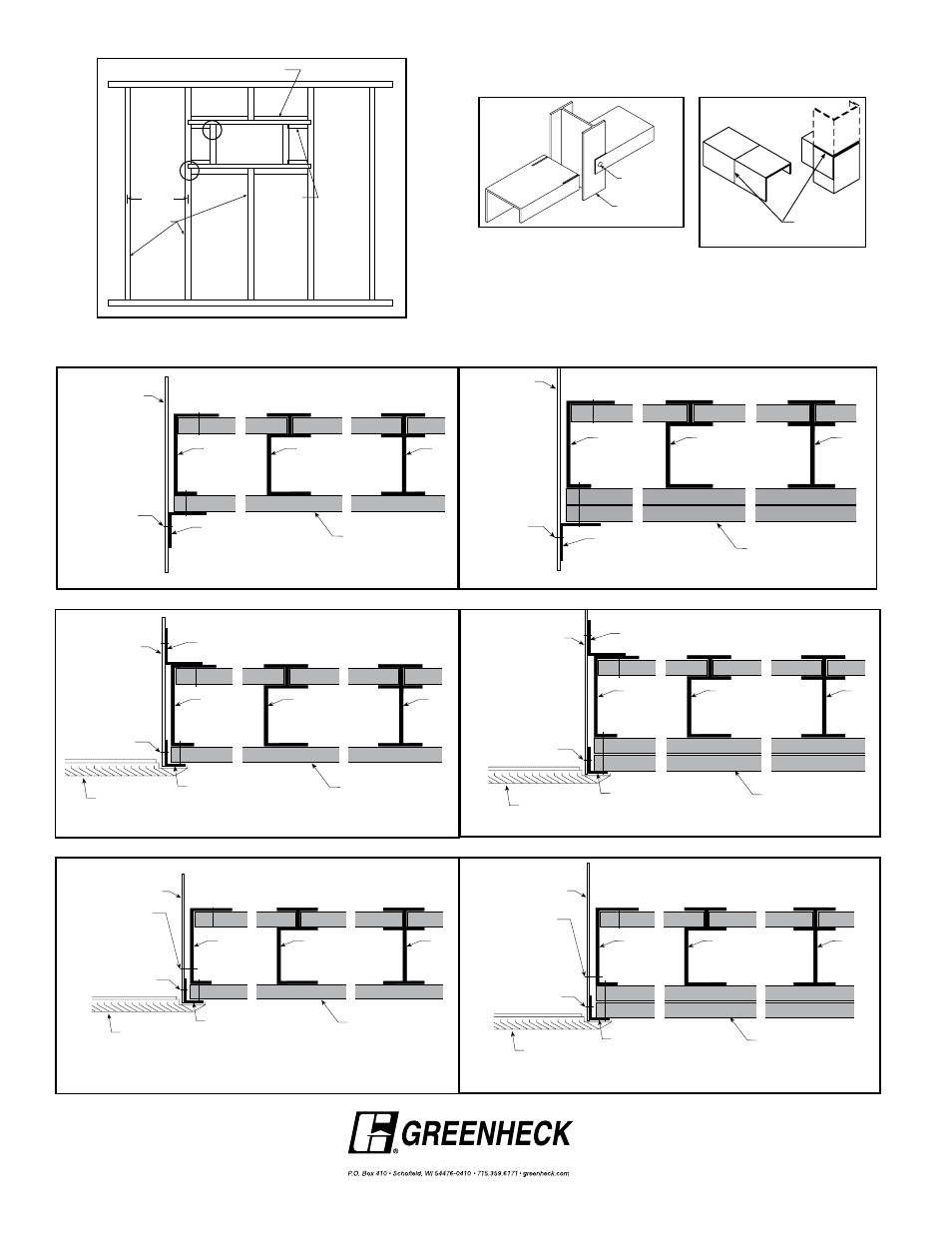
Detail ‘B’: Forming J-Track
Cut here and
bend down
Copyright © 2013 Greenheck Fan Corporation.
462100 Metal Stud in Cavity Shaftwall Rev. 12 Jan 2013
5
/
8
in. UL Classified
Gypsum Wallboard (see UL
Rated Wall Design for
Additional Details)
J-Runner
C-H Stud
I-Stud
Damper
Sleeve
Angle Fastener
(see Note 2)
Retaining Angle
(See Note 2)
Figure #3: 1 Hour Shaftwall Rating
J-Runner
C-H Stud
I-Stud
Damper
Sleeve
Two layers of
5
/
8
in. UL
Classified Gypsum Wallboard
(see UL Rated Wall Design for
Additional Details)
Angle Fastener
(see Note 2)
Retaining Angle
(See Note 2)
Figure #4: 2 Hour Shaftwall Rating
5
/
8
in. UL Classified
Gypsum Wallboard (see UL
Rated Wall Design for
Additional Details)
J-Runner
C-H Stud
I-Stud
Damper
Sleeve
Angle Fastener
(see Note 2)
Grille (supplied
by others)
Retaining angle
(See Section 2)
Retaining angle
(See Note 2)
Figure #5: 1 Hour Shaftwall Rating
J-Runner
C-H Stud
I-Stud
Damper
Sleeve
Angle Fastener
(see Note 2)
Grille (supplied
by others)
Retaining Angle
(See Section 2)
Retaining Angle
(See Note 2)
Two layer of 5/8 in. UL
Classified Gypsum
Wallboard (See UL
Rated Wall Design for
Additional Details)
Figure #6: 2 Hour Shaftwall Rating
�
5
/
8
in. UL Classified
Gypsum Wallboard (see UL
Rated Wall Design for
Additional Details)
J-Runner
C-H Stud
I-Stud
Damper
Sleeve
Angle Fastener
(see Note 2)
Grille (supplied
by others)
#10 sheet metal screws
spaced 6 in. on center and
a maximum of 2 in. from
the corners (minimum of 2
screws per side). Screw
into studs so as to avoid
space conflicts with the
grille assembly.
Retaining angle
(See Note 2)
Figure #7: 1 Hour Shaftwall Rating
J-Runner
C-H Stud
I-Stud
Damper
Sleeve
Two layers of 5/8
� in. UL
Classified Gypsum Wallboard
(see UL Rated Wall Design
for Additional Details)
Angle Fastener
(see Note 2)
Grille (supplied
by others)
#10 sheet metal screws
spaced 6 in. on center and
a maximum of 2 in. from
the corners (minimum of 2
screws per side). Screw
into studs so as to avoid
space conflicts with the
grille assembly.
Retaining angle
(See Note 2)
Figure #8: 2 Hour Shaftwall Rating
24 in.
O.C.
Maximum
I-Studs
J-Track Headers (Slot ends to fit into
I-Studs as shown in Detail ‘A’)
J-Track folded
as shown in
Detail ‘B’.
Attach to J-
Track header
Detail ‘B’
Detail ‘A’
Figure #2: Optional Opening Preparation
Detail for I-Stud Assembly
Detail ‘A’: J-Track to I-Stud
Connection
Fasten J-Track
in this manner
I-Stud