Installation, Warning – Greenheck Low Voltage (24 VAC/ VDC) Sure-Aire Pressure Controller (476092) User Manual
Page 2
2
Sure-Aire™ Flow Monitoring System
Installation
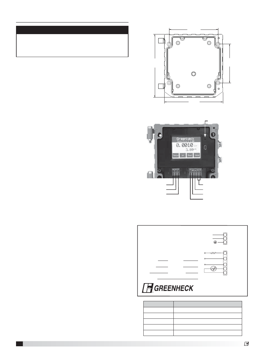
1. Mount the controller in the vertical plane using four
#8-32 screws. Open the front cover by unscrewing
the two captive thumb screws to gain access to the
four mounting locations pictured at right.
Note: Mount the Sure-Aire controller within 75 feet
of the termination plate on the fan.
2. Use 1/4-inch nylon tubing to connect the
corresponding high and low, 1/4-inch quick connect,
pressure ports of the Sure-Aire controller to the high
and low pressure ports of the termination plate on
the fan.
3.
Remove terminal block TB1 and perform wiring for
the pins listed below. For liquid tight applications,
use only 1/2-inch liquid tight conduit.
Terminal Block TB1: Input Power
Pin 1 = 24V, AC or DC (+ or -)
Pin 2 = 24V, AC or DC (+ or -)
Pin 3 = Earth Ground
4. Provide power to the controller to turn it on.
5. Select the desired Output Signal of the controller
for the Building Automation System. Use the touch
screen to select the 4-20 mA or 2-10 Vdc output
signal via the controller’s setup menu. (Refer to
Display Setting Options and Setup section, Output
Signal, pages 3 and 4).
6.
Wire TB2 appropriately for the selected Output
Signal in Step 5.
Terminal Block TB2: Transmitter/Temperature
Sensor
Pin 1 = 4-20 mA or 2-10 Vdc (+) (output)
Note:
4 to 20 mA requires a load resistor
200-900 ohms
Pin 2 = 4-20 mA or 2-10 Vdc (-) (output)
Pin 3 = Shield
Pin 4 = Remote Temperature Sensor (input)
Pin 5 = Remote Temperature Sensor (input)
Note: Signal isolator may be required when two or
more output signals share a common connection at
the PLC/controller.
7. If temperature compensation is desired, mount the
provided temperature sensor in contact with the
airstream. Wire the temperature sensor into TB2
and change Temperature Comp to “Yes” via the
controller’s setup menu.
8. When the above steps are completed, make sure the
front cover is properly aligned to the housing and the
two captive thumb screws are securely tightened.
Part Number
Description
384986
CNTRL,SURE-AIRE,0-8.3
384987
CNTRL,SURE-AIRE, 0-22.14
384988
CNTRL,SURE-AIRE, 0-41.52
384989
CNTRL,SURE-AIRE, 0-83.04
384990
CNTRL,SURE-AIRE, 0-138.40
Label and Order Information
The label providing details pertaining to the purchase
order is located on the inside cover of the controller.
Equipment
for
Measurement
Schofield, WI 54476 U.S.A.
Description: CNTRL,SURE-AIRE,0-22.14”
Fan Model: QEP Fan Size: 36
K Factor: 1967
Elevation: 1100
P/N: 384987
Sales Order: 6606573
Tag Mark: SF-1
P.O.#0843 Date Code: 8/12
24 Volts
AC or DC
6VA Max
Input Power
Earth Ground
~24 V
~24 V
1
2
3
TB1
4 to 20 mA/
2-10 Vdc (+)
4 to 20 mA/
2-10 Vdc (-)
Shield
Temperature
Sensor
Load Resistance
200-900 Ohms
1
2
3
TB2
4
5
4-5/32 in.
(105.6 mm)
5-3/8 in.
(136.5 mm)
3-9/32 in.
(83.3 mm)
5 in.
(127 mm)
Dimensions and Hole Mounting Pattern
Wiring and System Components
Temperature Sensor
Shield
4-20 mA / 2-10 Vdc (-)
4-20 mA / 2-10 Vdc (+)
24V, AC or DC
24V, AC or DC
Earth Ground
High
Pressure
Port
Reset Button
Low
Pressure
Port
TB1
TB2
WARNING
When wiring the instrument, you must follow industry
standard practices for control and protection against
electrostatic discharge (ESD). Failure to exercise good
ESD practices may cause damage to the controller.
®