Greenheck Hooded Propeller Roof Fans Filtered Supply (455602) User Manual
Assembly instructions, Filtered supply, Step 1: unpack and inspect parts
1
Model
1
Hooded Propeller Roof Fans • Filtered Supply
Part Number 455602
Hooded Propeller Roof Fans
Filtered Supply
Assembly Instructions
Please read these instructions carefully before attempting to assemble the product described. Protect
yourself and others by observing all safety information. Failure to comply with instructions could result
in personal injury and/or property damage!
®
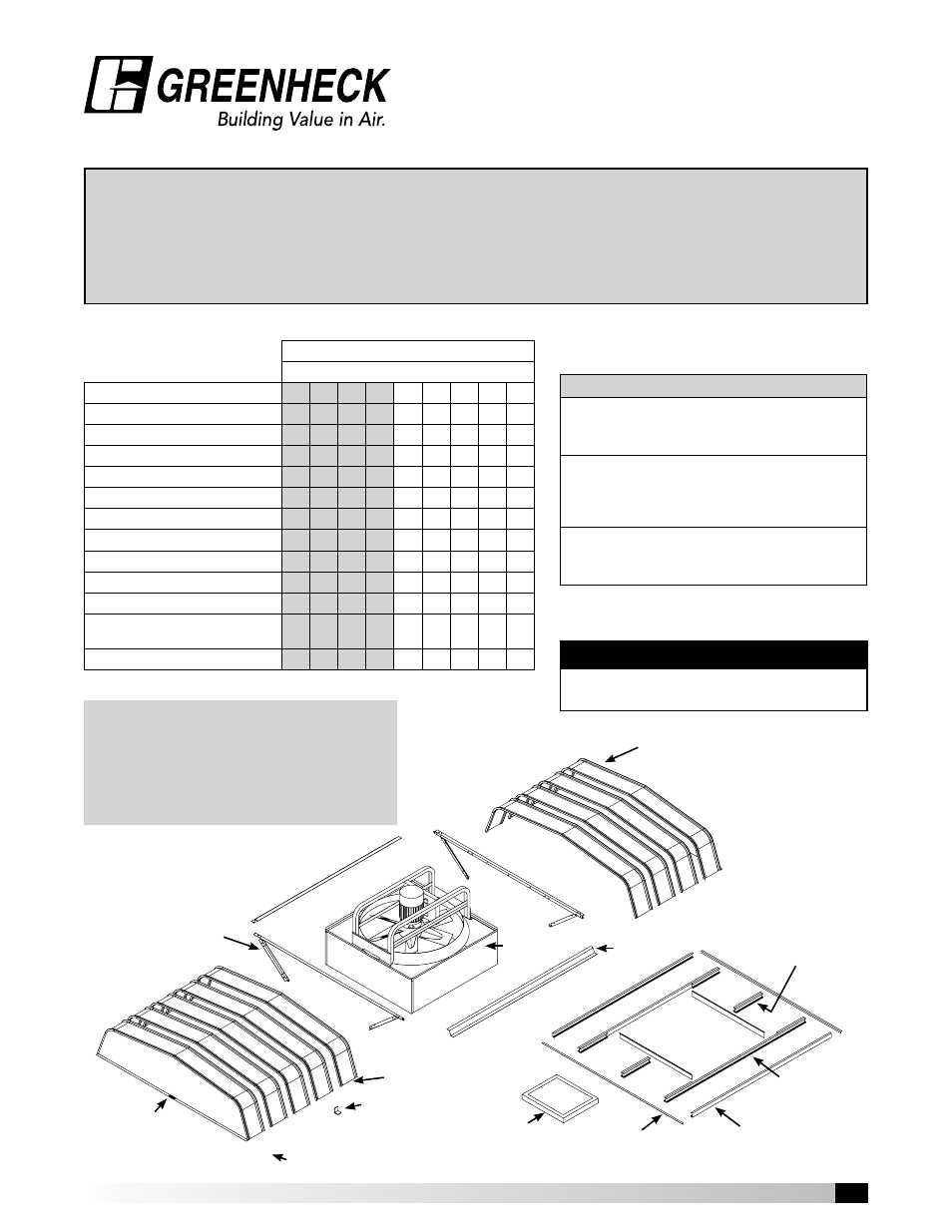
Step 1: Unpack and Inspect Parts
Filtered Supply Fans
Fan Size / Quantity of Parts per Fan Size
Parts Description
20 24 30 36 42 48 54 60 72
Fan / Base Assembly
1
1
1
1
1
1
1
1
1
Hood Support Rail Assembly
2
2
2
2
2
2
2
2
2
Outer Filter Channel
2
2
2
2
2
2
2
2
2
Inner Filter Channel
2
2
2
2
2
2
2
2
2
Filter End Channel
2
2
2
2
2
2
2
4
4
Filter Retaining Angle
2
2
2
2
2
2
2
2
2
End Filter Angle
2
2
2
2
2
2
2
2
2
End Filters
4
4
4
4
4
4
4
6
6
Side Filters
8
8
8
8
8
8
8
10 10
Hood Rails
2
2
2
2
2
2
2
2
2
Hood Enclosure Panels
- 1 male and 1 female panel
4
5
7
7
8
9
10 11 12
Hood Clips for sizes 48 - 72
-
-
-
-
-
16 18 20 22
Shaded sizes will always ship fully assembled unless otherwise specified.
Tools required to assemble fans:
• Drill, Electric or pneumatic preferred.
• 3/8”, 7/16”, 1/2”, and 9/16” wrenches and sockets
• 5/16” nut runner bit for drill
• Rubber mallet
• Awl for hole alignment
Hood Enclosure Panel
(Male)
Filter End
Angles
Outer Filter
Channel
Each fan that is shipped knocked down has the
following hardware package PN 816529 containing:
Hood Enclosure Panel
(Female)
Typical filter channel set is shown.
Quantity of filter end channels
varies by fan size.
Hood Support Rail
Hood Panels
Hood Clips
(Sizes 48 - 72)
Label
Filter
Inner Filter
Channel
Filter End
Channel
Hood Rail
Fan Base
IMPORTANT
It is recommended that a two man crew
minimum be used for fan/hood assembly.
Part Number 816529 - Hardware Package includes
Part Number 816526 - Hood Support Fasteners
(16) 3/8” - 16 x 3/4” Spinlock Bolts
(12) 3/8” - 16 Spinlock Nuts
Part Number 816527 - Hood Fasteners
(75) #12 x 3/8” Sheet Metal Screws with Washer
(4) 3/8” - 16 x 1-1/2” Spinlock Bolts
(4) 3/8” - 16 Spinlock Nuts
Part Number 816528 - Birdscreen / Filter Fasteners
(26) 5/16” - 18 x 3/4” Weld Stud Bolts
(26) 5/16” - 18 Spinlock Nuts
Note: Hardware package is designed for the filtered 72 inch
fan. When used on smaller sizes, there will be some fasteners
left over.