Instructions, Siemens gnd series – Greenheck GND Series Internal Mount (473707) User Manual
Page 2
Copyright © 2010 Greenheck Fan Corporation
473707 GND Series Rev. 1 May 2010
Instructions
Siemens GND Series
These installation instructions assume a damper is
already mounted in a duct or sleeve. Have damper
blades in the fail position.
1. Drill (2) .203 inch holes in the third blade from
bottom, at location shown in Detail A.
2. Attach blade drive lever to blades using (2) 1/4”
20 x 1/2” thread cutting screws, self drilling
screws or 1/4” - 20 x 1 1/4” bolts.
3. Fasten internal actuator bracket (item 1) to the
left jamb of damper frame using (2) thread cutting
screws. Snap bearing (item 11) into the internal
actuator bracket (item 1).
4. Snap bearing (item 11) into the anti-rotation
bracket (item 7) and attach to the internal mount
bracket (item 1) using [2] thread cutting screws
(item 9).
5. Slide 1/2” diameter rod (item 5) slightly through
the anti rotation bracket (item 7). Install crankarm
(item 3) and drive link (item 2) onto the 1/2”
diameter rod and (item 5) and install retaining
ring (item 12) to lock drive link onto the internal
actuator bracket (item 1).
6. Install threaded mounted stud (item 8) to the anti
rotation bracket (item 7) using #10-32 Keps nut
(item 6).
7. Attach actuator (item 10) to the anti-rotation
bracket assembly (item 7). Tighten actuator onto
shaft.
8. Connect drive link to blade drive lever using
e-clip. With blades closed and the actuator in its
fail position, position blades in their fail position
and tighten the crankarm to the 1/2 in. shaft.
9. Connect all electrical leads to the actuator. Apply
power to the actuator. The damper blades should
power position and return to the fail position
when power is disconnected.
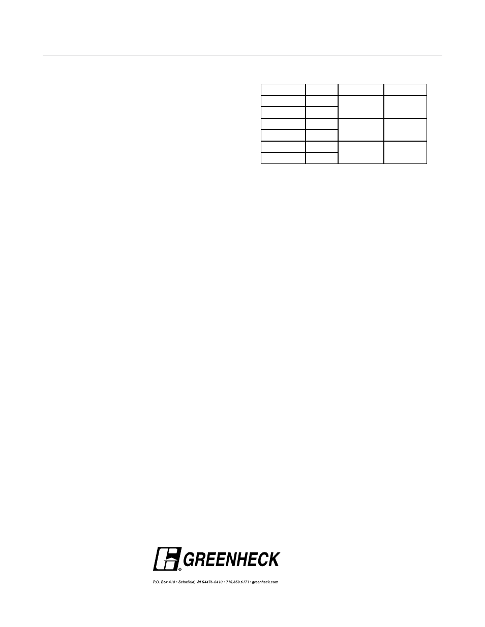
Model
Volts
Running
Holding
GND121.1
24
0W
0W
GND126.1
24
GND221.1
120
0
0
GND226.1
120
GND321.1
230V
0
0
GND326.1
230V