Installation, Duct collar mounting, Resistive temperature detector(s) (rtd) mounting – Greenheck Digital Temperature Interlock (474750 IOM) (Pre November 2012) User Manual
Page 3: Control box mounting, Instr, adj. temp interlock in flat spot, Top view of exhaust hood, Digital temperature interlock
3
Digital Temperature Interlock
®
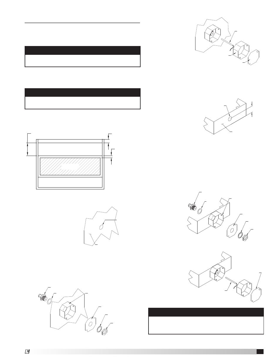
Duct Collar Mounting
1. Locate the exhaust duct on top of the hood. A 3/4
to 7/8-inch
(19.0 to 22.2 mm)
diameter
hole must
be cut into the duct 2 inches
(50.8 mm)
above the
hood top. Center
the hole along
the side of the
duct. Make sure
that the resistive
temperature
detector will not
interfere with any
fire system nozzles, or other items installed in the
exhaust duct. If an exhaust fire damper is present
the hood exhaust collar, it must be removed prior
to temperature sensor installation.
2. Place the J-box plate inside of the octagon
extension ring and place over the hole in the
exhaust collar.
3. Disassemble the compression seal and place
through
hole in duct
collar and
J-box plate
as shown.
Tighten the
nut inside
the octagon
extension
ring.
4. Place the resistive temperature detector
through the
compression
seal and
tighten the
compression
fitting.
5. Install the
cover for the
octagon box.
NOTE
Resistive temperature detector(s) may be factory
installed. If so, continue to the next section.
Resistive Temperature Detector(s)
(RTD) Mounting
Installation
Control Box Mounting
Locate an area with enough space to mount the
control box and fasten to the wall.
NOTE
All field installation and wiring of electrical
equipment must be done to meet NEC and local
codes.
2. Cut a 3/4 to 7/8-inch diameter hole in the flat
spot of the capture
tank. Make sure the
resistive temperature
detector(s) will not
interfere with fire
system nozzles and is
not within 12 inches of
light fixtures.
CAD Drawing from Tyler Schilling
Emailed to Barb on March 22, 2011
Octagon Extension
PN 830125
Lock Washer
Nut
Compression Seal
PN 463570
Gasket
J-Box Plate
PN 732396
Resistive Temperature
Detector (RTD)
PN 384439
Octagon Cover
PN 380926
3 inch air space
2 inch typical
19.525 inches
Octagon Extension
PN 830125
0.75 to 0.875 inch
(19.0 to 22.2 mm)
diameter hole
Hood Surface
1
2
3
1.
PLACE THE J-BOX PLATE INSIDE OF THE OCTAGON EXTENSION
RING, AND PLACE OVER HOLE.
2.
DISASSEMBLE THE COMPRESSION SEAL AND PLACE THROUGH
THROUGH HOLE AND J-BOX PLATE AS SHOWN. TIGHTEN THE NUT
INSIDE THE OCTAGON EXTENSION RING.
1.
PLACE THE THERMOSTAT THROUGH THE COMPRESSION
COMPRESSION SEAL AND TIGHTEN THE COMPRESSION FITTING.
2.
INSTALL THE COVER FOR THE OCTAGON BOX.
CUT A 0.75" - 0.875" HOLE IN THE FLAT SPOT OF THE
CAPTURE TANK OF THE HOOD. KEEP 12" AWAY FROM
ANY LIGHT FIXTURE.
Sensor Install
(cutout area)
Exhaust Area
Supply Area
(optional)
HOOD PLAN VIEW
P.O.BOX 410 SCHOFIELD, WISCONSIN 54476-0410
TITLE
DRAWN BY
ECO
B
ENG. REF.
DATE
SUPERSEDES
SCALE
CAD DRAWING NO.
MROCZENSKI_L
12/02/2009
1/4
IAN29890
INSTR, ADJ. TEMP
INTERLOCK IN FLAT
SPOT
5. Place the resistive
temperature
detector through
the compression
seal and tighten
the compression
fitting.
6. Install the cover
for the octagon
box.
NOTE
Control box may be factory mounted. If so, continue
to the next section.
1. Locate flat area(s) at the top interior of the hood in
front of the filters, towards the front of the hood.
CAD Drawing from Tyler Schilling
Emailed to Barb on March 22, 2011
Octagon Extension
PN 830125
Lock Washer
Nut
Compression Seal
PN 463570
Gasket
J-Box Plate
PN 732396
Resistive Temperature
Detector (RTD)
PN 384439
Octagon Cover
PN 380926
3 inch air space
2 inch typical
19.525 inches
Octagon Extension
PN 830125
0.75 to 0.875 inch
(19.0 to 22.2 mm)
diameter hole
Hood Surface
1
2
3
1.
PLACE THE J-BOX PLATE INSIDE OF THE OCTAGON EXTENSION
RING, AND PLACE OVER HOLE.
2.
DISASSEMBLE THE COMPRESSION SEAL AND PLACE THROUGH
THROUGH HOLE AND J-BOX PLATE AS SHOWN. TIGHTEN THE NUT
INSIDE THE OCTAGON EXTENSION RING.
1.
PLACE THE THERMOSTAT THROUGH THE COMPRESSION
COMPRESSION SEAL AND TIGHTEN THE COMPRESSION FITTING.
2.
INSTALL THE COVER FOR THE OCTAGON BOX.
CUT A 0.75" - 0.875" HOLE IN THE FLAT SPOT OF THE
CAPTURE TANK OF THE HOOD. KEEP 12" AWAY FROM
ANY LIGHT FIXTURE.
Sensor Install
(cutout area)
Exhaust Area
Supply Area
(optional)
HOOD PLAN VIEW
P.O.BOX 410 SCHOFIELD, WISCONSIN 54476-0410
TITLE
DRAWN BY
ECO
B
ENG. REF.
DATE
SUPERSEDES
SCALE
CAD DRAWING NO.
MROCZENSKI_L
12/02/2009
1/4
IAN29890
INSTR, ADJ. TEMP
INTERLOCK IN FLAT
SPOT
Top View of Exhaust Hood
CAD Drawing from Tyler Schilling
Emailed to Barb on March 22, 2011
Octagon Extension
PN 830125
Lock Washer
Nut
Compression Seal
PN 463570
Gasket
J-Box Plate
PN 732396
Resistive Temperature
Detector (RTD)
PN 384439
Octagon Cover
PN 380926
3 inch air space
2 inch typical
19.525 inches
Octagon Extension
PN 830125
0.75 to 0.875 inch
(19.0 to 22.2 mm)
diameter hole
Hood Surface
1
2
3
1.
PLACE THE J-BOX PLATE INSIDE OF THE OCTAGON EXTENSION
RING, AND PLACE OVER HOLE.
2.
DISASSEMBLE THE COMPRESSION SEAL AND PLACE THROUGH
THROUGH HOLE AND J-BOX PLATE AS SHOWN. TIGHTEN THE NUT
INSIDE THE OCTAGON EXTENSION RING.
1.
PLACE THE THERMOSTAT THROUGH THE COMPRESSION
COMPRESSION SEAL AND TIGHTEN THE COMPRESSION FITTING.
2.
INSTALL THE COVER FOR THE OCTAGON BOX.
CUT A 0.75" - 0.875" HOLE IN THE FLAT SPOT OF THE
CAPTURE TANK OF THE HOOD. KEEP 12" AWAY FROM
ANY LIGHT FIXTURE.
Sensor Install
(cutout area)
Exhaust Area
Supply Area
(optional)
HOOD PLAN VIEW
P.O.BOX 410 SCHOFIELD, WISCONSIN 54476-0410
TITLE
DRAWN BY
ECO
B
ENG. REF.
DATE
SUPERSEDES
SCALE
CAD DRAWING NO.
MROCZENSKI_L
12/02/2009
1/4
IAN29890
INSTR, ADJ. TEMP
INTERLOCK IN FLAT
SPOT
3. Place the J-box plate inside of the octagon
extension ring and place over the hole.
4. Disassemble the compression seal and place
through hole and J-box plate as shown. Tighten the
nut inside the octagon extension ring.
Octagon Extension
PN 830125
Lock Washer
Nut
1/4-inch Compression Seal
PN 463570
J-Box Plate
PN 732396
Resistive Thermostat
Detector (RTD)
PN 384439
Octagon Cover
PN 380926
2 inches
(50.8 mm)
Hood Exhaust Collar
Front Side
0.75 to 0.875 inch
(19.0 to 22.2 mm)
diameter hole
Quik Seal
Gasket
1
2
3
1.
PLACE THE J-BOX PLATE INSIDE OF THE
OCTAGON EXTENSION RING, AND PLACE OVER
HOLE IN THE EXHAUST COLLAR.
2.
DISASSEMBLE THE COMPRESSION SEAL AND PLACE
THROUGH HOLE IN DUCT COLLAR AND J-BOX
PLATE AS SHOWN. TIGHTEN THE NUT INSIDE THE
OCTAGON EXTENSION RING.
1.
PLACE THE THERMOSTAT THROUGH THE
COMPRESSION SEAL AND TIGHTEN THE
COMPRESSION FITTING.
2.
INSTALL THE COVER FOR THE OCTAGON BOX.
CUT A 0.75" - 0.875" HOLE, CENTERED LEFT TO RIGHT
AND 2" FROM THE BOTTOM.
P.O.BOX 410 SCHOFIELD, WISCONSIN 54476-0410
TITLE
DRAWN BY
ECO
B
ENG. REF.
DATE
SUPERSEDES
SCALE
CAD DRAWING NO.
MROCZENSKI_L
12/02/2009
1/4
IAN29890
CAD Drawing from Tyler Schilling
Emailed to Barb on March 22, 2011
INSTR, ADJ. TEMP
INTERLOCK IN DUCT
COLLAR