Checkout, Preliminary inspection, Flame signal measurement (fig. 4) – Greenheck Amplifier for 7800 Series Relay Module User Manual
Page 6
R7824, R7847, R7849, R7861, R7886 AMPLIFIERS FOR 7800 SERIES RELAY MODULES
65-0109—6
6
5. Use recommended wire size and type no. 18 copper
conductors TTW(60C) or THW (75C) or THNN(90C).
6. Use recommended wire routing:
a.
Keep the flame signal leadwire as short as
possible from the detector to the 7800 SERIES
Relay Module. The maximum permissible leadwire
length depends on the type of leadwire, conduit
type and leadwire diameter. The ultimate limiting
factor for flame signal leadwire length is the flame
signal voltage.
b.
Do not run high voltage ignition transformer wires
in the same conduit with the flame detection wiring.
c.
If the flame detector leadwires are not long
enough to reach the 7800 SERIES Relay Module
electrical connectors, make splices in a junction
box.
1. Enclose scanner wiring without armor cable in
metal cable or conduit.
2. Follow flame detector Instructions.
7. Check wiring, see Fig. 4.
8. Install 7800 SERIES Relay Module.
9. Restore power to the 7800 SERIES Relay Module.
Flame detector wiring is shown in Fig. 3.
CHECKOUT
Preliminary Inspection
Make certain that:
1 Wiring connections are correct and all terminal screws
and electrical connections are tight.
2 Proper flame failure response time is selected.
3 Amplifier is securely mounted on the 7800 SERIES
Relay Module.
4 Detectors are properly positioned and cleaned
according to Detector Instructions.
5 Correct combination of amplifier and flame detector is
used.
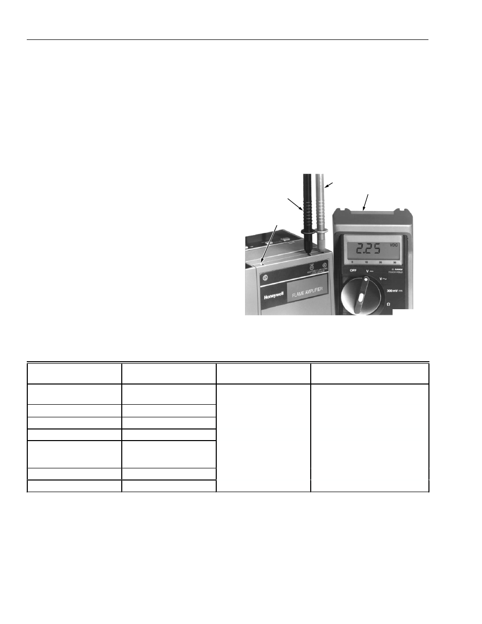
Flame Signal Measurement (Fig. 4)
Flame signal can be measured at the Flame Signal Test
Jacks, see Fig. 4, and at the Keyboard Display Module.
Measure the flame signal at the appropriate times defined in
the Checkout section; see applicable 7800 SERIES Relay
Module Instructions. See Table 3 for acceptable and
maximum flame signal voltage strengths.
Table 3. Flame signal.
a
This minimum or stronger signal can be easily obtained if the detector is correctly installed and positioned to properly sense
the flame. Obtain this voltage before completing checkout.
b
The flame amplifiers are Ampli-Check® type.
c
Adjust slightly, or face the pipe down, or extend the sight pipe on C7012A,C,E,F applications to obtain a maximum flame signal
reading less than 5.0 volts.
d
The flame signal amplifier circuitry is tested one-half second every five seconds during burner operation and shuts down the
burner if the amplifier fails (all installations).
e
R7824C, Series 2 or greater, and R7847C, Series 4 or greater, pulse the shutter when the flame signal reaches 1.5 Vdc.
Fig. 4. Flame signal measurement with meter.
Flame Detector
Flame Signal Amplifier
Minimum Acceptable
Steady dc Voltage
a
Maximum Expected dc Voltage
Flame Rod Photocell
C7012A,C
c
R7847A,B
b
1.25 Vdc
5.0 Vdc at Keyboard Display
Module or on volt-ohmmeter
e
C7012E,F
c
R7847C
d,e
C7015A
R7848A,B
b
C7024E,F
R7824C
d,e
C7027A
C7035A
C7044A
R7849A,B
b
C7061A
R7861A
d
C7076A,D
R7886A
d
NEGATIVE (-)
METER LEAD
POSITIVE (+)
METER LEAD
ONE
MEGOHM/VOLT
METER
M11459A
FLAME SIMULATOR
TEST JACK