Instructions, Wiring illustration – Greenheck AFB Series Actuators External Mount (464236 IOM) User Manual
Page 2
Instructions:
These installation instructions assume the damper is already
mounted in a duct or sleeve with the damper shaft extending
beyond the duct or sleeve 6 inches.
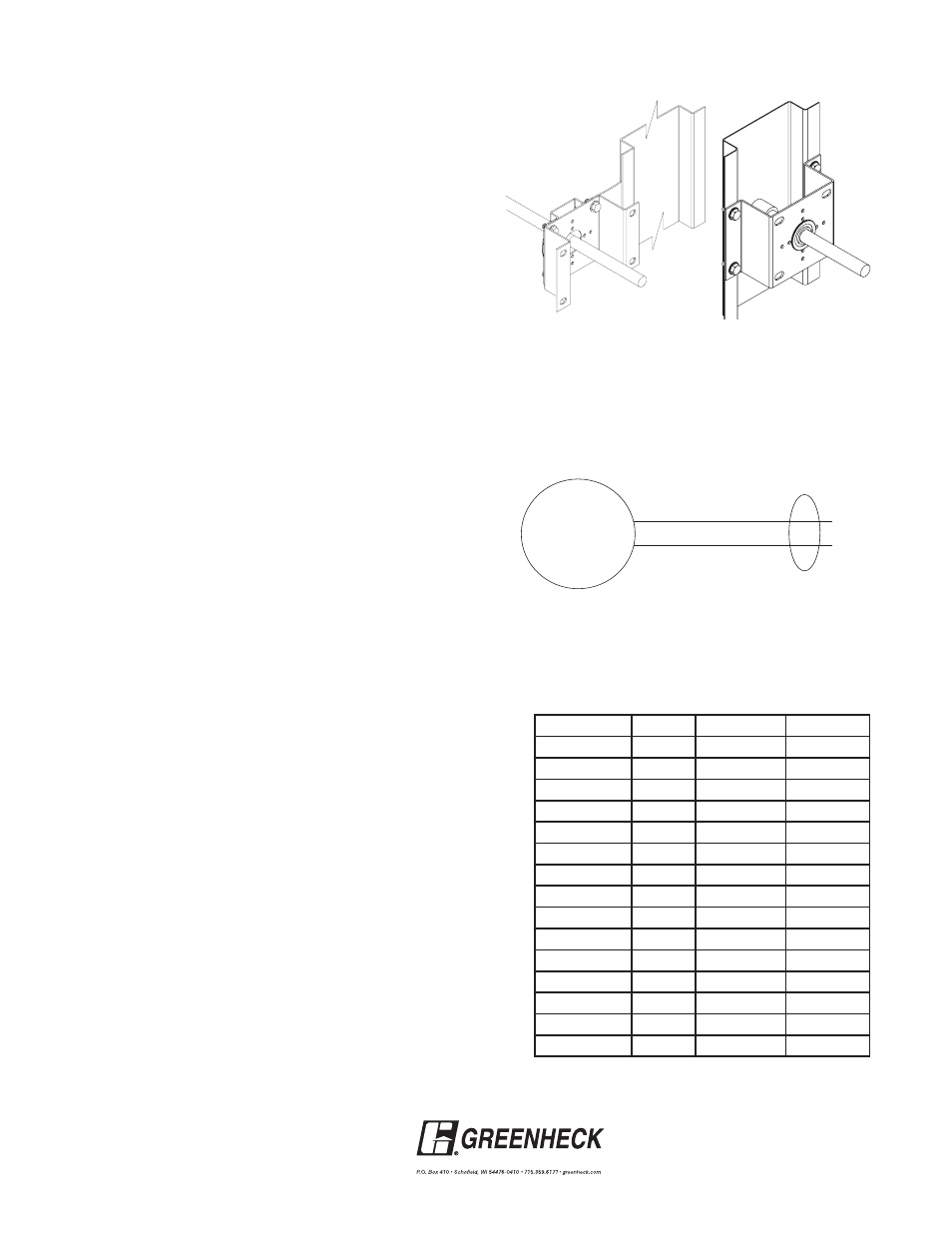
1. Install the stand off bracket.
Dampers with a jackshaft
1a. Jackshaft supplied is typically 1 in. (25mm) diameter. For
these applicaitons the bearing must be removed from the
stand-off bracket (item 3). Mount the stand-off bracket
(item 3) with (4) thread studs and (4) 1/4 -20 spinlock
screws.
Dampers without a jackshaft (Shaft Extension)
1b. Mount the stand off bracket (item 3) spanning across
the damper frame flanges. Orient the anchor bracket
perpendicular to the damper on the duct or sleeve so that
the bracket shaft hole is centered on the shaft extension.
Fasten to the damper frame with (4) #14 Tek screws (item
6) or equal, supplied by others. Be sure not to run the
screws into the damper linkage, which is between the
flanges.
2. If the fail rotation of the damper is counter clockwise, this is a
Left Hand installation and the universal clamp should be on
the side labeled CCW on the actuator (usually shipped in this
orientation). If the fail rotation of the damper is clockwise, this
is a Right Hand installation and the universal clamp should be
on the side labeled CW on the actuator.
To change the universal clamp from one side to the other
side, remove the retaining clamp and then the universal clamp
from the actuator. Replace the universal clamp on the correct
side of the actuator making sure that the corresponding tab is
pointing to 0° and the spline pattern of the clamp fits onto the
actuator. Slip the clamp on and then lock in place using the
retaining clamp.
Note: All fail rotations refer to the damper shaft rotation
needed to achieve the desire blade fail position. If fail position
is closed, make sure damper blades are fully close and ensure
blade seals are compressed prior to tightening the actuator
clamp to the damper extension pin or jackshaft. Inspect the
damper blades and the damper shaft to determine the proper
damper shaft rotation for the desired blade fail position.
3. Slide the actuator and the mounting bracket onto the damper
shaft making sure the anti-rotation strap is in the slot on the
actuator. Mount the mounting bracket to the stand off bracket
using (4) 1/4 in.-20 x 1/2 in. bolts and (4) 1/4 in. - 20 Spinlock
nuts, included with this kit. Use the outer four holes of the
mounting bracket for jackshafted models and the inner four
holes for directly driven models.
Note: The mounting bracket may be attached in three
positions: parallel with the duct, perpendicular up from the
duct, or perpendicular down from the duct. Choose a position
that offers the most clearance for the application.
4. Verify that the damper is in its fail position. Tighten the universal
clamp to the damper shaft.
5. The wiring illustration to the right identifies actuator electrical
connections. Wiring should be per an approved project or job
wiring diagram and must comply with all applicable electrical
codes.
6. Apply power to the actuator. The damper blades should fully
open or close and return to the fail position when power is
disconnected. No adjustments are required.
Black
White
120 Volt or
24 volt
M
Wiring Illustration
Orientation of Stand Off
Bracket for a directly driven
damper
Orientation of Stand Off
Bracket for a jackshaft
driven damper
Copyright © 2010 Greenheck Fan Corporation
464236 Belimo IOM Rev. 6 Nov 2010
Model
Volts
Running
Holding
AFBUP
24-240
7W
3.5W
AFBUP-S
24-240
7W
3.5W
AFB24-MFT
24
7.5W
3W
AFB24-MFT-S
24
7.5W
3W
FSAF-24
24
7.5W
2W
FSAF-24S
24
7.5W
2W
FSAF-120
120
9.5W
3.5W
FSAF-120S
120
9.5W
3.5W
FSAF-230
230
11W
3.5W
FSAF-230S
230
11W
3.5W
FSNF-24
24
18W
6W
FSNF-120
120
18W
6W
FSNF-230
230
18W
6W
NFB24-SR
24
3.5W
2.5W
NFB24-SR-S
24
3.5W
2.5W
Wiring Illustration