Caution – Greenheck 7800 Series Relay Modules User Manual
Page 9
RM7895A,B,C,D/EC7895A,C; RM7896A,B,C,D 7800 SERIES RELAY MODULES
9
66-1090—2
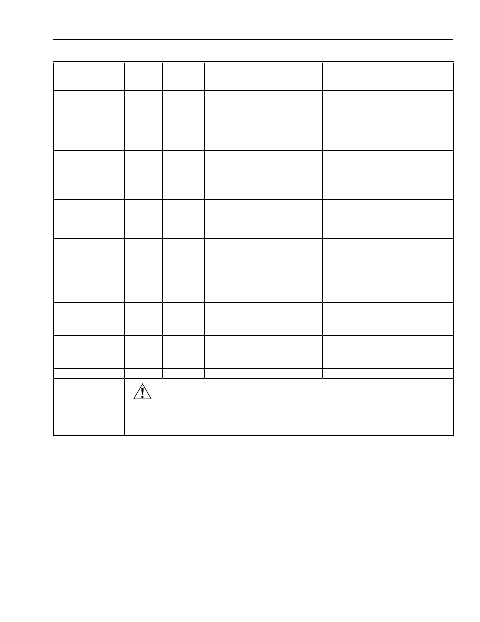
Table 6. Static Checkout.
Test
No.
Relay
Module
Model
Test
Jumpers
Voltmeter
Normal Operation
If Operation is Abnormal, Check
Items Listed Below
1
All
None
5-L2
Line voltage at terminal 5.
1.
Master switch.
2.
Power connected to master switch.
3.
Overload protection (fuse, circuit
breaker, etc.) has not opened
power line.
2
All
None
6-L2
Line voltage at terminal 6.
1.
Limits.
2.
Burner controller.
3
All
4-5
7-L2
1.
Burner motor (fan or blower)
starts.
2. Line voltage at terminal 7
within 10 seconds.
1.
Burner motor circuit.
a.
Manual switch of burner motor.
b.
Burner motor power supply,
overload protection and
starter.
c.
Burner motor.
4
All
5-10
—
1.
Ignition spark (if ignition
transformer is connected to
terminal 10).
1. Watch for spark or listen for buzz.
a.
Ignition electrodes are clean.
b.
Ignition transformer is okay.
5
All
5-8
—
1.
Ignition spark (if ignition
transformer is connected to
terminal 8).
2.
Automatic pilot valve opens (if
connected to terminal 8).
NOTE: Refer to wiring diagram of
system being tested.
1.
Watch for spark or listen for buzz.
2.
Listen for click or feel head of valve
for activation.
a.
Actuator if used.
b.
Pilot valve.
6
All
5-9
—
Automatic fuel valve(s) open(s).
If using direct spark ignition, check
first stage fuel valve(s) instead of
pilot valve.
Same as test 5. If using direct spark
ignition, check first stage fuel valve(s)
instead of pilot valve.
7
EC7895CR
M7895C,D,
RM7896C,D
5-21
—
Automatic second stage main fuel
valve(s) opens.
1.
Listen for and observe operation of
second stage main fuel valve(s)
and actuator(s).
2.
Valve(s) and actuator(s).
8
All
5-3
—
Alarm (if used) turns on.
1.
Alarm.
Final
All
CAUTION
Equipment Damage Hazard.
Can cause equipment damage.
After completing these tests, open master switch and remove all test jumpers from subbase
terminals. Also remove bypass jumpers, if used, from low fuel pressure limits.
Mounting RM7895A,B,C,D/EC7895A,C;
RM7896A,B,C,D Relay Module
1. Mount the RM7895A,B,C,D/EC7895A,C;
RM7896A,B,C,D vertically on the Q7800 Subbase or
mount horizontally with the knife blade terminals
pointing down. When mounted on the Q7800A, the
RM7895A,B,C,D/EC7895A,C; RM7896A,B,C,D must
be in an electrical enclosure.
2. When mounting in an electrical enclosure, provide
adequate clearance for servicing, installation and
removal of the RM7895A,B,C,D/EC7895A,C;
RM7896A,B,C,D, KDM, flame amplifier, flame amplifier
signal voltage probes, electrical signal voltage probes
and electrical connections.
a.
Allow an additional two inches (51 mm) below the
RM7895A,B,C,D/EC7895A,C; RM7896A,B,C,D
for the flame amplifier mounting.
b.
Allow an optional three-inch (76 mm) minimum on
both sides of the RM7895A,B,C,D/EC7895A,C;
RM7896A,B,C,D for electrical signal voltage
probes.
3. Make sure no subbase wiring is projecting beyond the
terminal blocks. Tuck in wiring against the back of the
subbase so it does not interfere with the knife blade
terminals or bifurcated contacts.
IMPORTANT
The RM7895A,B,C,D/EC7895A,C; RM7896A,B,C,D
must be installed with a plug-in motion rather than a
hinge action.