Geist Leak Detection Kit User Manual
Page 5
Leak Detection Kit quick setup guide (rev.131111B-GD)
5
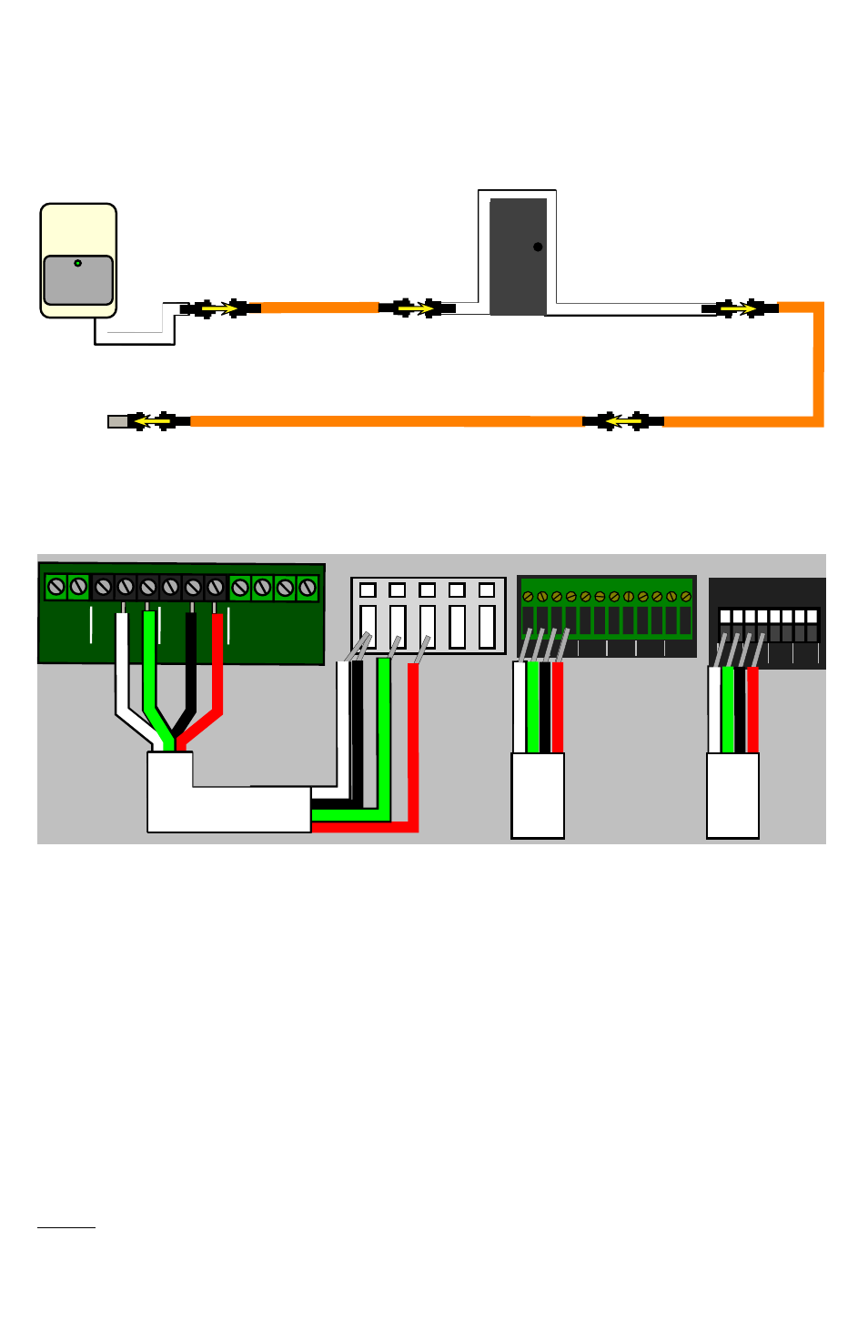
Ÿ Connecting the relays to a monitoring unit:
Using the 4-conductor alarm wire supplied with the kit (or any suitable 4-conductor wire),
with the relay mode jumper in “supervised” mode, connect the signals between the LD300
control box and the monitoring unit’s analog-input terminal block as shown here:
wire
color
LD300
Control Box
RSE-series
monitors
RSO or GBB-series
monitors
white
FAULT C
left C
C
green
FAULT NO
1
1
black
LEAK C
left C
C
red
LEAK NO
2
2
On an RSE-style terminal block, both the white and black wires can be inserted into the
same ‘C’ terminal; on the RSO and GBB-series units, each numbered analog input has its
own corresponding ‘C’ terminal. (The different terminal-block styles are illustrated
above.) Note that the use of inputs #1 and #2 here is merely an example; any of the
numbered analog inputs can be used, as long as the red and green wires are connected to
different inputs, and those inputs don’t already have other sensors connected to them. You
cannot, however, connect both the red and green wires to a single analog input; the “fault”
and “leak” signals must be connected to separate inputs for the unit to work properly.
5VDC
DC IN
–
+
NC
NC
NO
NO
C
C
FAULT
LEAK
CABLE
INPUT
B
W
R
G
C
C
1
2
3
C
1
C
2
C
3
C
4
ANALOG INPUTS
Dry Contact / 0-5VDC
C 1 C 2 C 3 C 4 C 5 C 6
POWER/ALARM
LD300
Non-Sensing Cable is used
to go around the door frame
Ÿ “Non-Sensing Cable” (optional):
Non-Sensing Cable, available as an optional accessory, is an economical way to route
around or over non-monitored spaces, such as doorways, or to give greater flexibility in
where to mount the control box without wasting Leak Detection Cable across areas where
there is no need to actually sense liquids. Non-Sensing Cable can be connected anywhere
within the chain.