Fronius Acctiva Twin 15A User Manual
Page 50
48
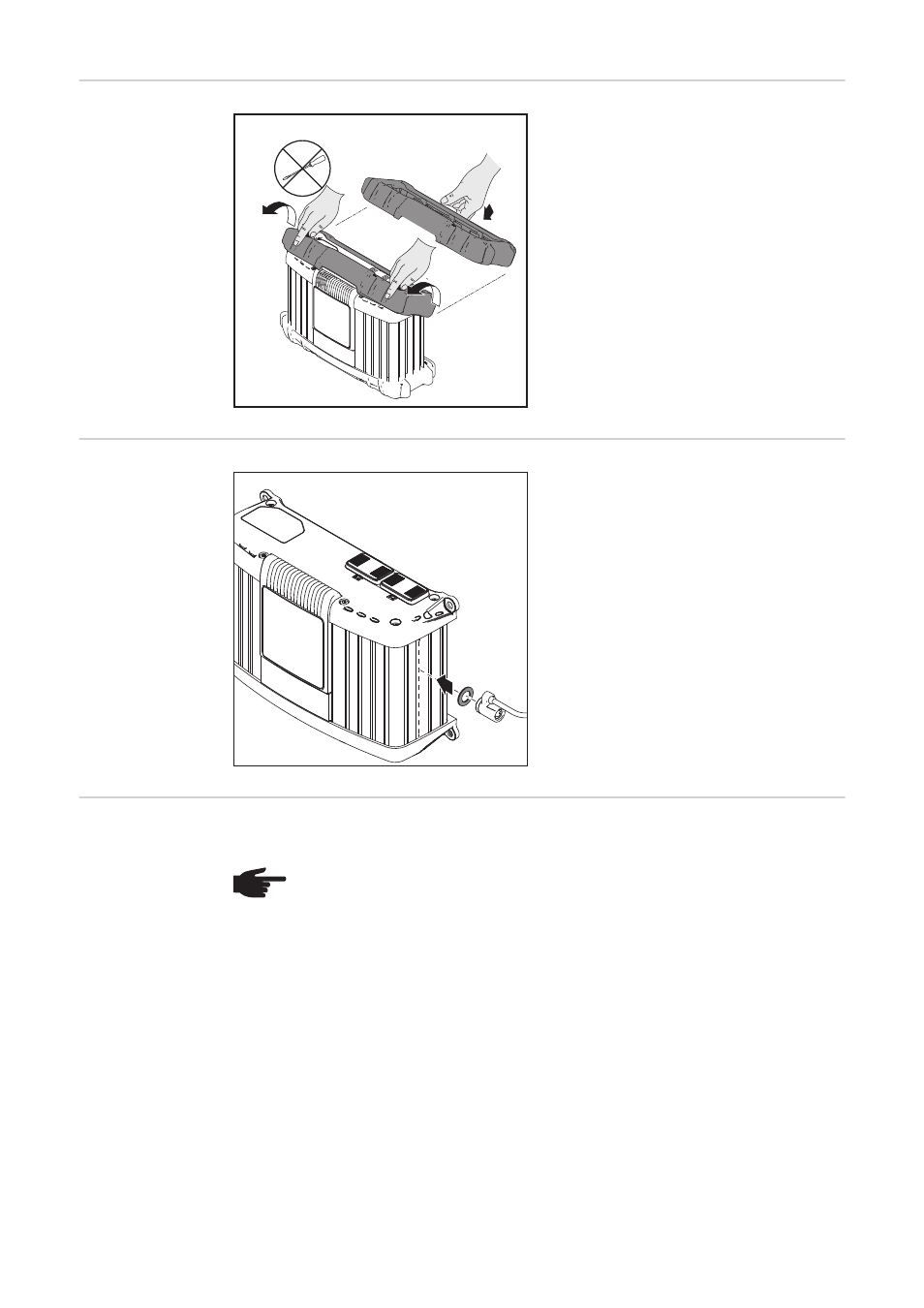
Optional edge
guard
The edge guard removal process is the re-
verse of the fitting process.
If the edge guard is fitted, the charger and
bracket cannot be wall- or floor-mounted
because the holes in the housing provided
for that purpose are covered.
Security lock
A security lock can only be attached
-
to the groove on the housing as shown
-
to the groove on the housing that is ex-
actly opposite
-
using spacer M8 DIN 125 or DIN 134,
located as shown
Installation
If installing the charger on a firm base, use drilling template enclosed in the packaging.
The space requirement measurements in mm (inches) illustrated below are given to en-
sure that there is easy access to the plug connections:
1
2
2
NOTE! IP40 is guaranteed for the upright position. If the charger is installed in a
switch cabinet (or similar separate area), then forced-air ventilation must be pro-
vided to ensure adequate heat dissipation. There should be a clearance of 10 cm
(3.94 in.) all around the charger.