Chapter 2 installation instructions – Foxconn P9657AA-8EKRS2H User Manual
Page 23
Chapter 2 Installation Instructions
16
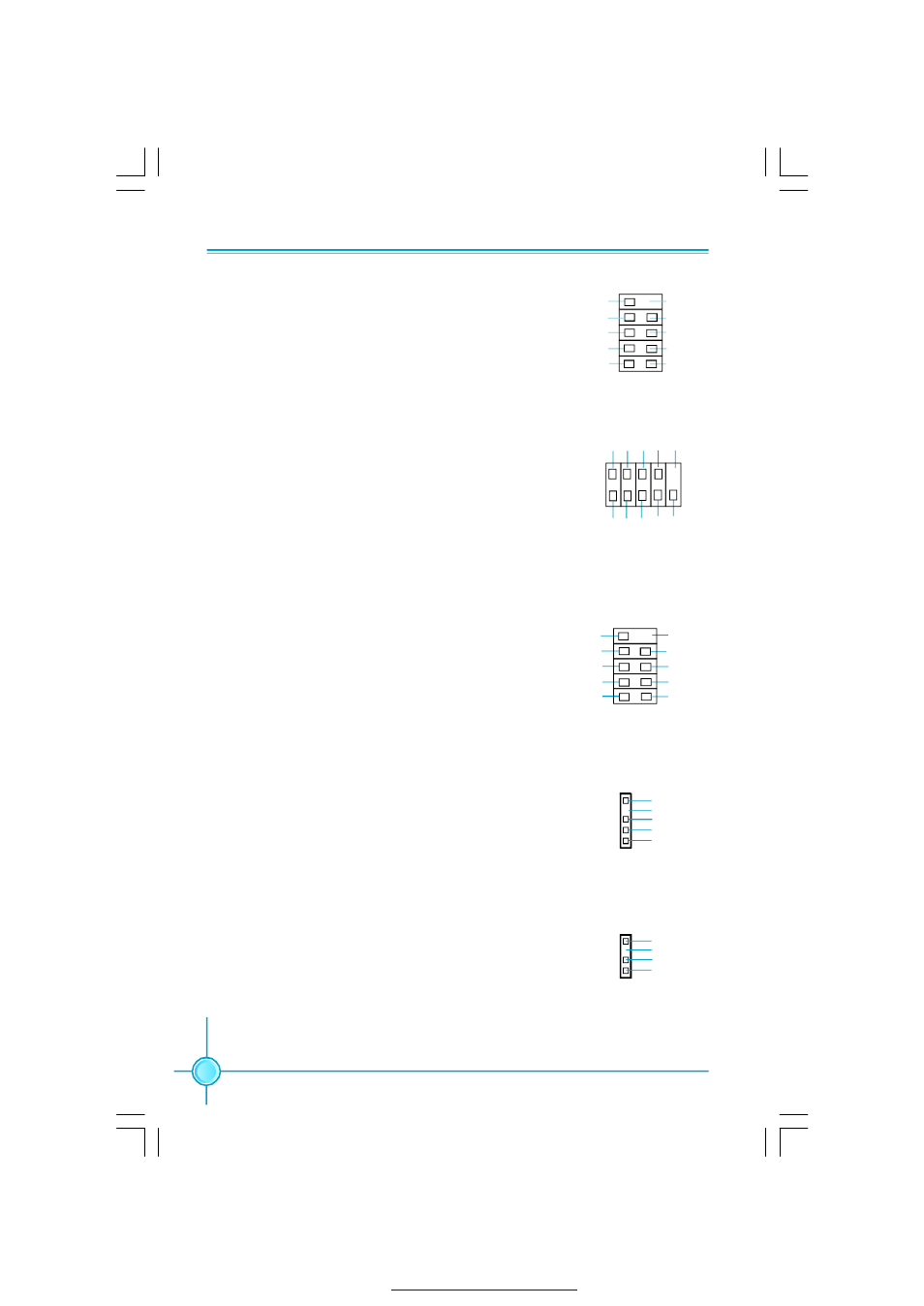
USB Headers: F_USB1, F_USB2, F_USB3
Besides four USB ports on the rear panel, the series of
motherboards also have three headers on board which
may connect to front panel USB cable (optional) to
provide additional six USB ports.
F_USB 1/2/3
1
5 V_ DUAL
D-
D+
D-
GND
GND
D+
NC
E mpty
5 V_ DUAL
Additional COM Connector: COM2 (optional)
This motherboard provides an additional serial COM
header for your machine.
Connect one side of a switching cable to the header,
then attach the serial COM device to the other side of
the cable.
1394 Connector:
F_1394 (optional)
The 1394 expansion cable can be connected to either
the front (provided that the front panel of your chassis
is eq uipp ed with the app ro priate in terfac e) o r real
panel of the chassis.
IrDA Connector: IR
This header supports wireless transmitting and receiv-
ing device. Before using this function, configure the
settings of IR Mode from the
“Integrated Peripherals”
section of the CMOS Setup.
1
2
GND
+12V
TPB -
GND
TPA -
+12V
TPB +
GND
TPA +
Empty
F_1394
9
10
COM2
SOUT
GND
RLSD
RI#
DTR#
DSR#
SIN
9
10
1
2
CTS#
RTS#
Empty
IR
1
+5V
GND
IRRX
I RTX
E mpt y
Speaker Connector: SPEAKER(optional)
The speaker connector is used to connect speaker of
the chassis.
SPEAKER
1
SPKJ
NC
SPKJ
E mpt y
PDF 文件使用 "pdfFactory" 试用版本创建