Controls – Dixon RAM 48ZT BF User Manual
Page 17
ContRols
17
This operator’s manual describes the dixon Zero Turn
rider. The rider is fitted with a Kohler or Briggs &
Stratton four-stroke overhead valve engine developing
24-26* horse power.
Transmission from the engine is made via two
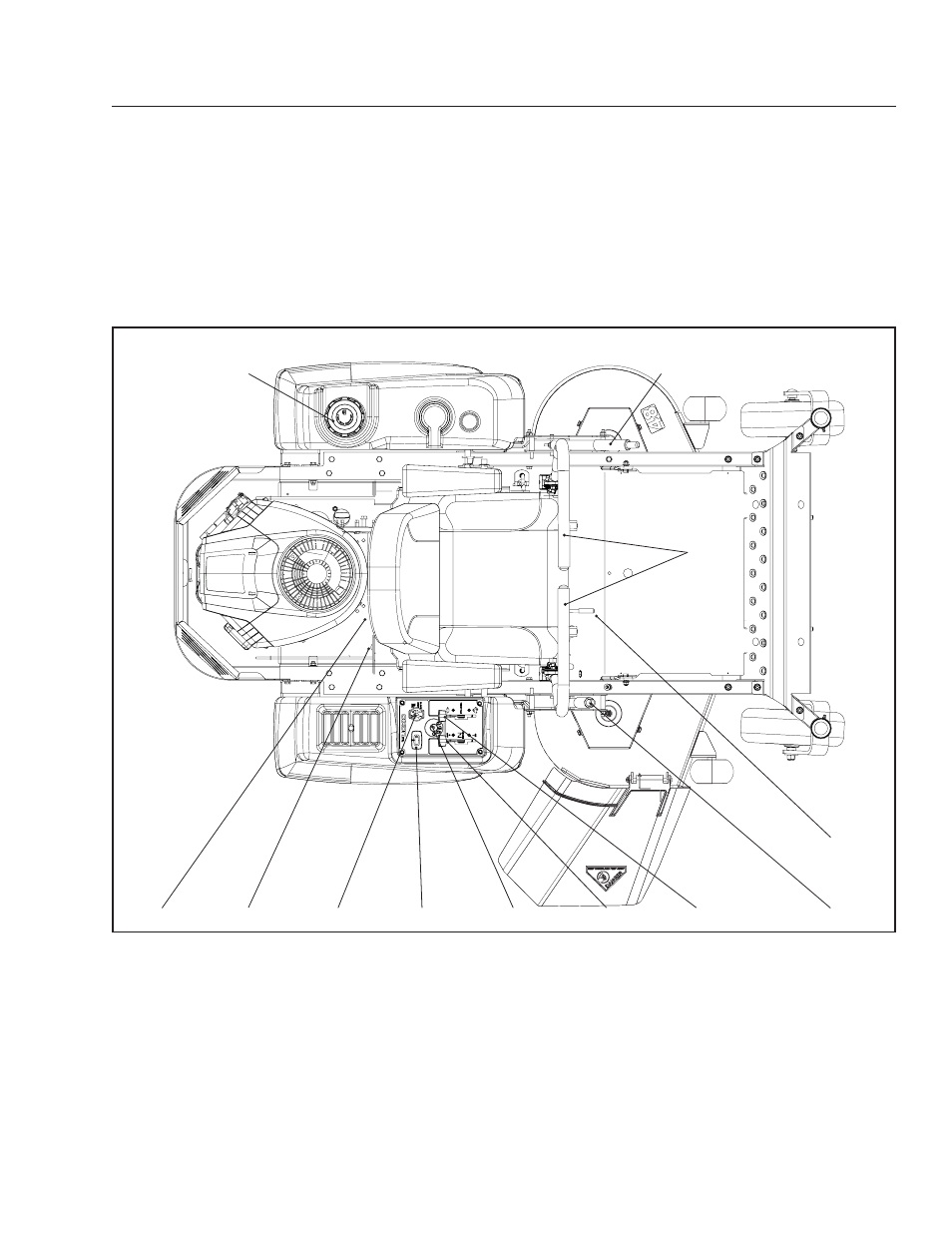
Control Locations
motion control levers
1.
Seat adjustment lever
2.
Cutting height adjuster
3.
Throttle control
4.
Choke control
5.
Ignition switch
6.
1
3
4
5
6
8
9
2
10
7
11
Hour meter
7.
Blade switch
8.
fuses
9.
fuel shut off valve
10.
fuel tank cap
11.
Parking brake
12.
12
belt-driven hydraulic pumps, which in turn drive a
hydraulic motor for each drive wheel. Using the left
and right steering controls, the flow is regulated and
thereby the direction and speed.
*
The power rating of the engines indicated is the average net power
output (at specified rpm) of a typical production engine for the
engine model measured to SAE standard J1349/ISO1585. Mass
production engines may differ from this value. Actual power output
for the engine installed in the final machine will depend on the
operating speed, environmental conditions and other variables.