2 layout – Foxconn A78AX-K User Manual
Page 11
1
4
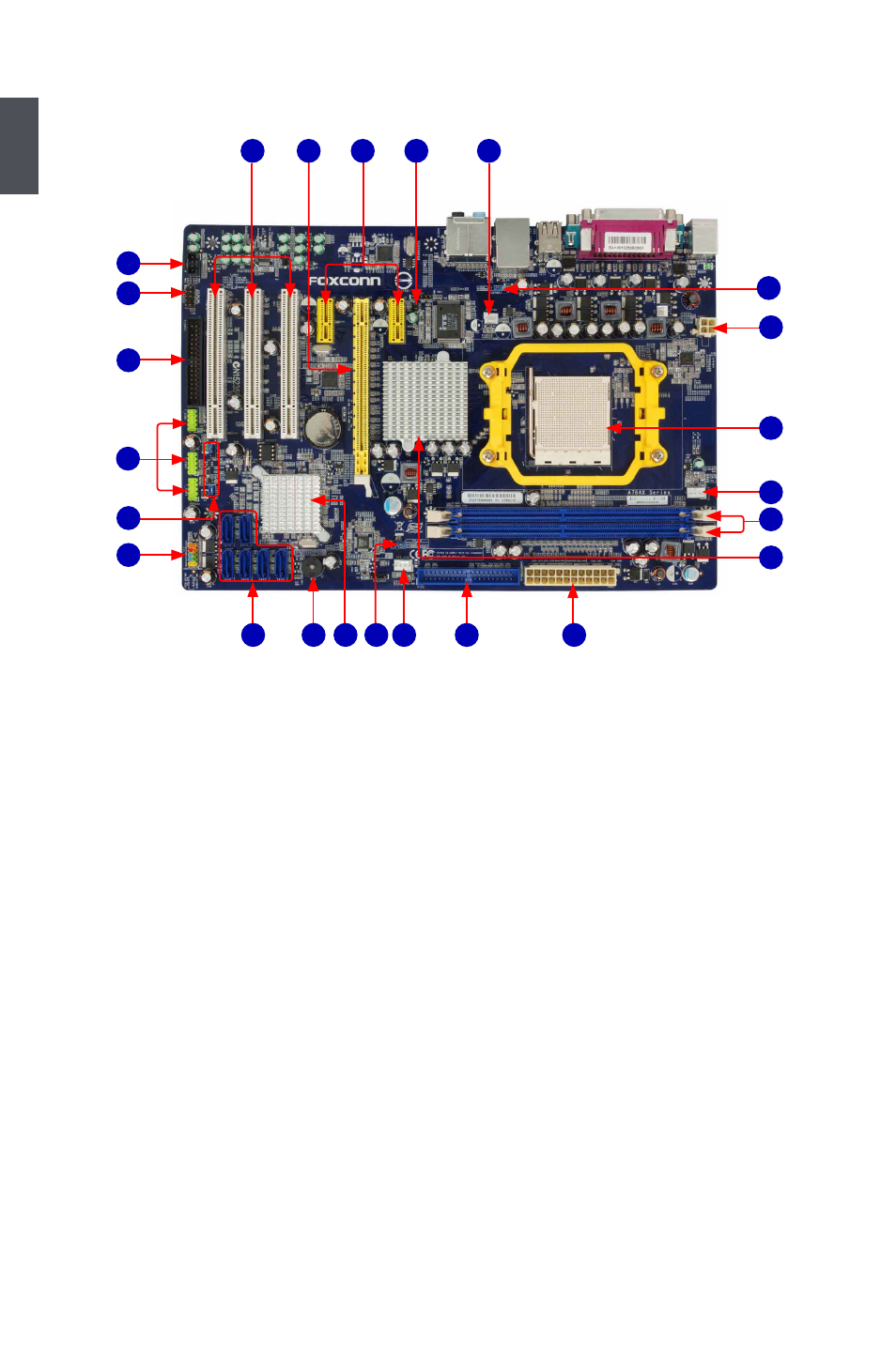
1-2 layout
1. NB (North Bridge) Fan Header
2. Chassis Intrusion Alarm Header
3. PCI Express x1 Slots
4. PCI Express x16 Slot
5. PCI Slots
6. CD_IN Connector
7. Front Audio Connector
8. Floppy Connector
9. Front USB Connectors
10. USBPWR2, USBPWR3 Jumper
11. Front Panel Connector
12. SATA Connectors
13. Buzzer
14. South Bridge: AMD SB700
15. Clear CMOS Jumper
16. System Fan Header
17. IDE Connector
18. 24-pin ATX Power Connector
19. North Bridge: AMD 770
20. DDR2 DIMM Slots
21. CPU Fan Header
22. CPU Socket
23. 4-pin ATX 12V Power Connector
24. USBPWR1 Jumper
Note : The above motherboard layout is for reference only, please refer to the physical
motherboard for detail.
1
2
5
4
7
8
9
11
6
10
22
21
20
23
19
12
13
17
16
18
15
14
24
3