How to connect the switch box, Qa-es automation bundle users manual, Figure 2. switchbox connections to qa-es ii – Fluke Biomedical QA-ES Automation Bundle User Manual
Page 14: Coag cut off
QA-ES Automation Bundle
Users Manual
6
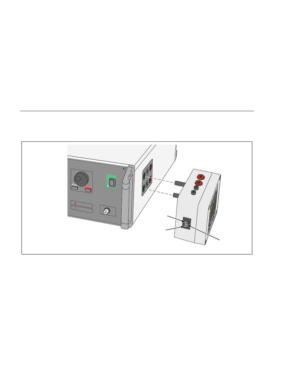
How to Connect the Switch Box
Before you do an ESU test with the ESU Analyzer, the
switch box must be connected to the foot switch output
jacks on the right side of the ESU Analyzer. See Figure 2.
Note
The three-position switch has a center off
position.
POWER
ENTER
CANCEL
RF-DETECT
REMOTE
SCOPE OUTPUT
EVERE
T
T
, W
A
9820
3
Coag
Cut
Off
giw13.eps
Figure 2. Switchbox Connections to QA-ES II
See also other documents in the category Fluke Biomedical Equipment:
- 7000DP Impulse Supplement (12 pages)
- 7000DP Impulse Getting Started (36 pages)
- 7000DP Impulse (92 pages)
- 06-526-2200 (26 pages)
- 07-417 (16 pages)
- 07-443 (14 pages)
- 07-451 (8 pages)
- 07-487 (12 pages)
- 07-453 (24 pages)
- 07-555 (8 pages)
- 07-553 (10 pages)
- 07-605-7777 (8 pages)
- 07-444 (46 pages)
- 07-618 (10 pages)
- 07-600 (6 pages)
- 07-591 (8 pages)
- SigmaPace 1000 (154 pages)
- 07-653 (8 pages)
- 07-633 (20 pages)
- 07-649 (14 pages)
- 07-661-7662 (12 pages)
- 07-645 (14 pages)
- 10100AT (80 pages)
- 07-644 (10 pages)
- 18-203 (4 pages)
- 07-621 (12 pages)
- 07-647 (12 pages)
- 18-207 (8 pages)
- 18-216-1000 (10 pages)
- 18-220 (10 pages)
- 18-228 (8 pages)
- 18-223 (18 pages)
- 18-229-1313 (6 pages)
- 18-250 (8 pages)
- 18-252 (6 pages)
- 18-303 (6 pages)
- 35035 (19 pages)
- 6000-528 (18 pages)
- 35080B (70 pages)
- 6000-529 (16 pages)
- 35080M (64 pages)
- 6000-530B (16 pages)
- 57-436 (12 pages)
- 57-440 (12 pages)
- 57-402 (32 pages)