Wiring, Fig. 10 – Flowserve NRGS 11-2 User Manual
Page 15
5
Wiring
NRGS 11-2, NRGS 16-2
■
Fuse supply cables with T 2.5 A.
Tools
Attention
■
Screwdriver for cross head (“Phillips”) screws, size
■
Screwdriver for slotted screws, size 2.5; completely insulated according to VDE 0680
■
Open-end spanner 7 mm A. F.
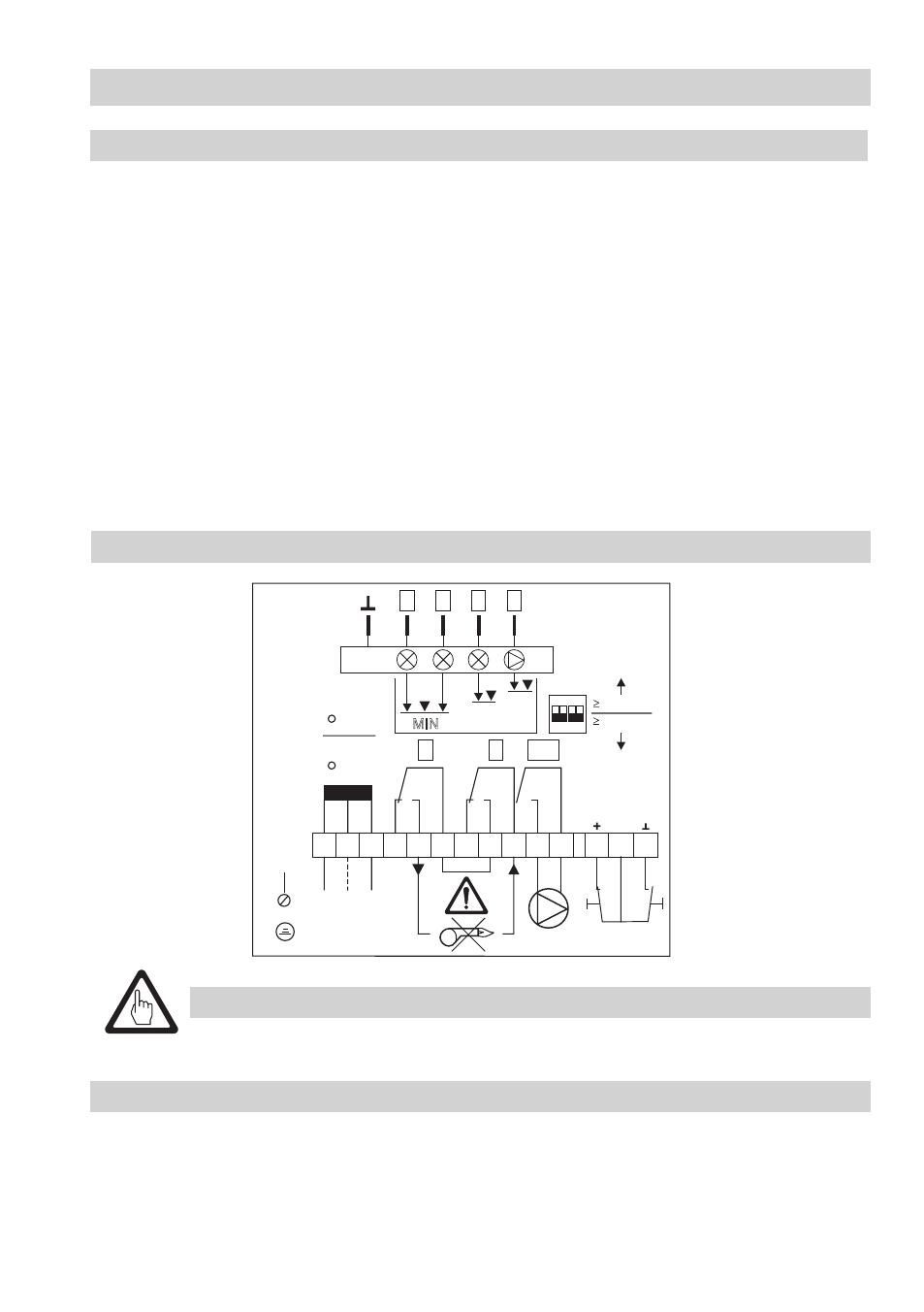
Fig. 10
1 2 3 4
ON
1 2 3 4 5 6 7 8 9 10 11 13 14 12
1
2
2
3/4
4
3
N
L
115
V
230
V
24
V
TEST RESET
Alarm
ON
MIN
PE
1
NRGS 11-2
NRGS 16-2
24V
Relays are shown in the
“power-off” position
(alarm condition)
Wiring diagram
Use multi-core flexible control cable with min. conductor size .5 mm² for wiring.
. Unscrew screws
E, remove housing cover G Fig. 4
2. Unscrew union nuts of cable entry
F.
The electrode terminal can be turned through +/- 180°.
3. Loosen plug
N with 7 mm open-end spanner but do not remove. Fig. 5
4. Turn electrode terminal into desired direction (+/- 80°).
5. Tighten plug
N slightly.
6. Remove terminal strip
J from board.
7. Connect terminal strip according to wiring diagram, connect PE connection
K.
8. Plug in terminal strips
J.
9. Install cable entry
F.
0. Replace housing cover
G, fasten screws E and install cable entry.
0 µS/cm
0.5 µS/cm
Mains