Installation – Flowserve NRGS 11-2 User Manual
Page 12
2
Attention
■
The seating surfaces of the threads or flange provided on the vessel or boiler standpipe
must be accurately machined.
Fig. 3
■
Do not bend electrode tip when mounting.
■
Do not lag electrode body.
Note
■
For the approval of the boiler standpipe with connecting flange the relevant local and
national regulations must be considered.
■
See four examples of installation on page 3.
Tools
■
Open-end spanner 4 mm A. F.
■
Bolt cutter
■
Hacksaw
■
Flat file, medium cut
Installation
NRGS 11-2, NRGS 16-2
. Determine required measuring lengths of electrode tips and enter data in
table 1, Fig. 2.
2. Cut electrode tips
1 , 2 , 3 and 4 accordingly.
The electrode tips
1 and 2 (low level limiter) must have the same length.
3. Deburr faces of electrode tips.
4. Strip off 50 mm of PTFE insulation from the ends of electrode tips.
5. Check seating surfaces of threads or flange provided on vessel or boiler standpipe.
Fig. 3
6. Place joint ring
C onto seating surface B of electrode Fig. 2. Use only joint ring
(of stainless steel .430) D 33 x 39 to DIN 7603 supplied with electrode.
7. Apply a light smear of silicone grease (e. g. DOW Corning Compound) to electrode thread
D.
8. Screw level electrode into threads or flange provided on vessel or boiler standpipe and tighten
with a 4 mm open-end spanner. The torque required is 40 Nm when cold.
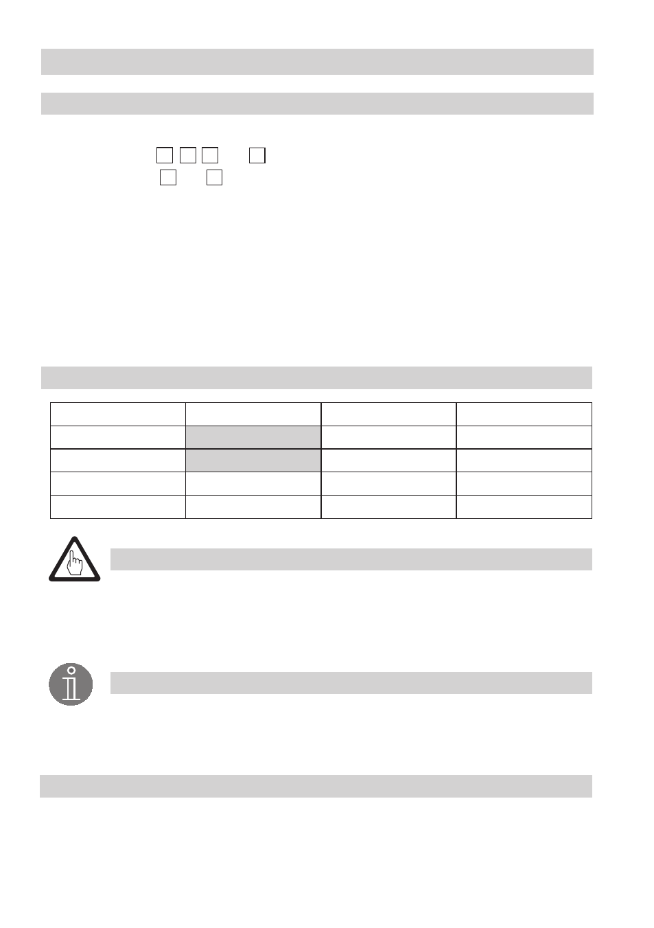
Table 1
Enter data here!
Function
Function
Electrode tip
Length [mm]
Low-level alarm
Low-level alarm
2
e. g. Pump ON
3
e. g. Pump OFF
4