Basic settings, Switching controller level electrode, Fig. 23 – Flowserve NRG 16-40 User Manual
Page 23
3
Basic Settings
continued
1
2
H
1
1
2
2
3
3
1 2 3
5 6 7
4
8 910
ON
1
2
3
4
5
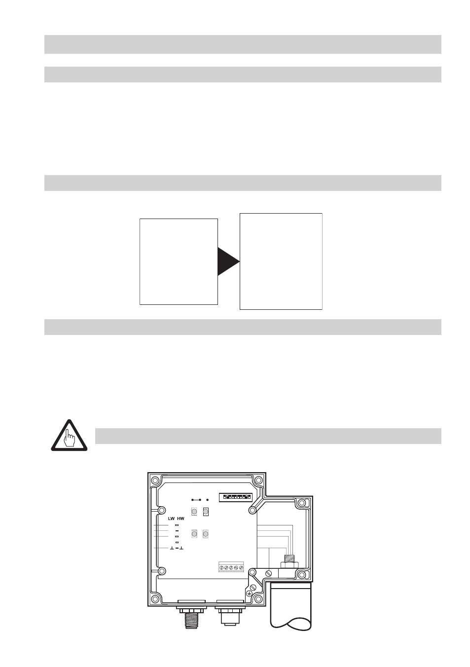
Fig. 23
Attention
■
Do
not assign the same node ID twice within the CAN bus network.
Assigning / changing node ID
If several systems of the same kind are to communicate in one CAN bus network, be sure to assign
one node ID for each individual system component (e. g. controller).
. Undo screws
H
and remove housing cover
J
.
. Change code switch
L
settings as required. For more information refer to page 4.
3. Re-attach housing cover
J
and fix it with screws
H
.
K
L
Water-level limiting system
The water-level limiting system consists of one switching controller type NRS -40 and
two level
electrodes type NRG ...-40. Before starting the system make sure to configure
one of the two level
electrodes as
level electrode 2.
■
Set wire link
K on circuit board to the right (electrode 2), Fig. 14
■
Set code switch
L according to the table "Node ID"
(example:
003*). For more information see Fig. 24 and 25 on page 4.
Factory set default node IDs
NRS 1-40
ID: 001
NRS 1-40.1 ID: 001
NRS 1-41
ID: 006
NRS 1-42
ID: 020
NRS 2-40
ID: 039
NRR 2-40
ID: 040
LRR 1-40
ID: 050
NRG 16-40 ID: 002
NRG 16-40 ID: 003
NRG 16-41.1 ID: 004
TRV 5-40
ID: 005
NRG 16-41 ID: 007
NRG 16-42 ID: 021
NRG 26-40 ID: 041
LRG 16-40
ID: 051
Switching Controller
Level Electrode