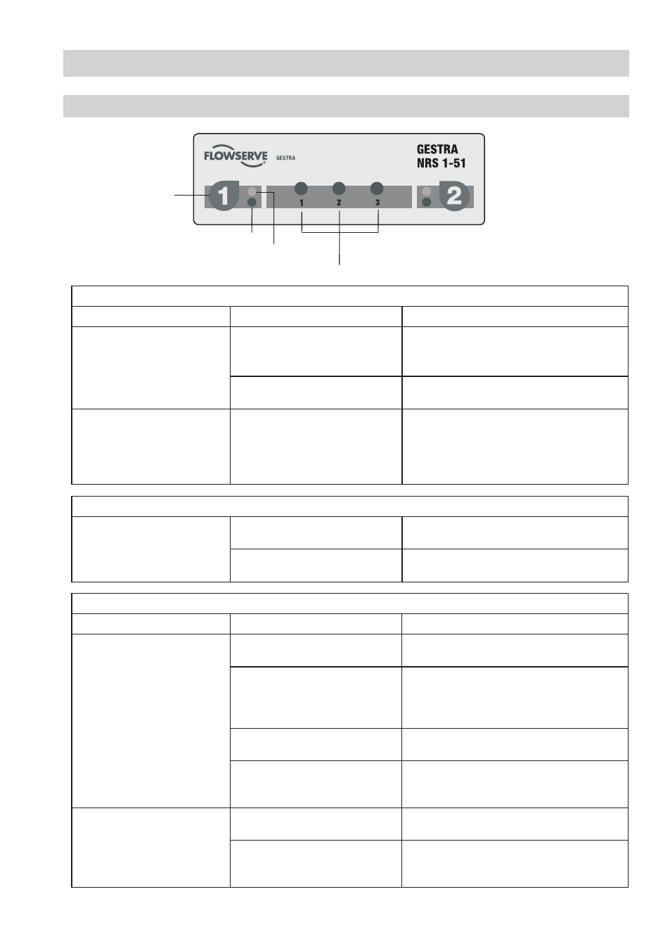
Commissioning procedure, Fig. 14 – Flowserve NRS 1-51 User Manual
Page 17
7
Commissioning Procedure
Checking switchpoint and function
Start
Activity
Indication
Function
Apply mains voltage.
All LEDs are illuminated.
System is being started and tested, this takes
approx. 0 sec. Output contacts are open.
Signal output closed.
All LEDs are illuminated for more
than 0 sec.
System malfunction. Possible causes:
Faulty power supply, level switch defective.
Lower water level in boiler
until the level falls below
the switchpoint high water
level (HW). Level electrode is
exposed.
Green LED
for level electrode is illuminated
Output contacts are closed.
Signal output is open.
Checking switchpoint and function
Raise level in boiler until the
switchpoint “high water level
(HW)” is ecxeeded. Level
electrode enters the water.
Red LED
for level electrode is flashing
De-energizing delay is running.
Signal output is closed instantaneously.
Red LED
for level electrode is illuminated
Delay time has elapsed, output contacts open.
Signal output is closed.
Possible installation faults
Status and indication
Fault
Remedy
Sightglass indicates high
water level (HW) exceeded,red
LED for level electrode is
not illuminated. Safety circuit
closed.
The electrode rod is too short.
Replace electrode rod and cut new rod to the
length dictated by the switchpoint HW.
The earth connection to the vessel
is interrupted.
Clean seating surfaces and screw in level
electrode with metallic joint ring. Do not
insulate the electrode with hemp or PTFE
tape!
Electrical conductivity of the boiler
water too low.
Set response sensitivity of the level switch to
0.5 μS/cm.
If installed inside the boiler: Upper
vent hole in protection tube does
not exist or is obstructed.
Check installation of level electrode. Make
sure that the level in the protection tube cor-
responds to the actual water level.
Water level sufficient. Red
LED for level electrode is
illuminated. Safety circuit is
open.
Electrode rod is too long.
Cut electrode rod to the length dictated by the
switchpoint HW.
Upper vent hole flooded.
Check installation of level electrode. Make
sure that the level in the protection tube
corresponds to the actual water level.
Level electrode 1
Test & diagnosis
button
LED alarm /
operating mode
Diagnosis LED
Fig. 14