Operation, Worcester controls – Flowserve 10 ACCESS I Worcester Controls User Manual
Page 6
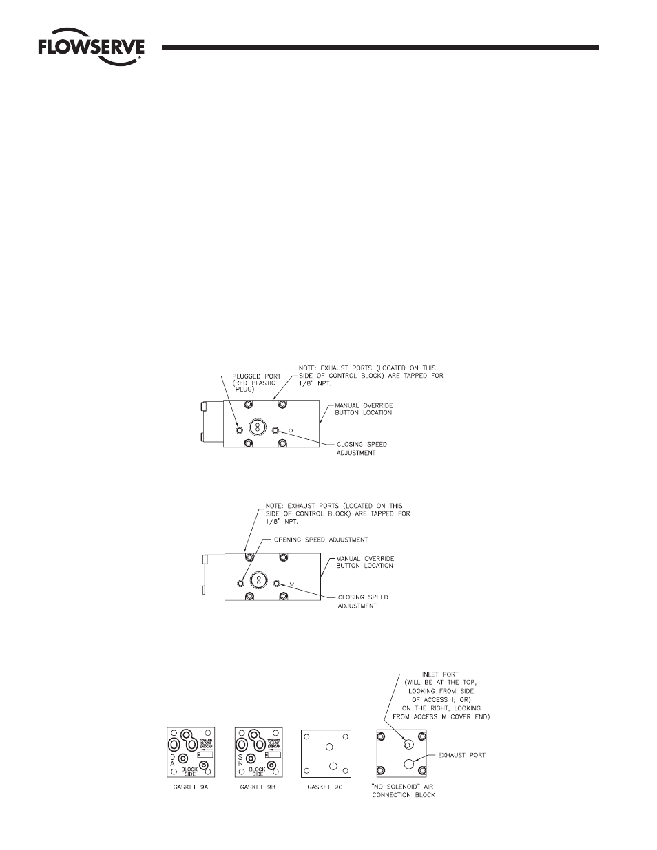
Figure 4
6
10, 15, 20 ACCESS I and 10-40 Access M 39 Actuators Intrinsically Safe
WCAIM2028
NOTE 3: The wiring diagrams shown in figure 3 are for specific
actuator positions/operations. For switch indications of other
positions/operations the actuator should be operated, and SW-1 and
SW-2 checked to verify which switch will give the desired indication.
5. Place the lubricated O-ring down over the threaded section of
the housing onto the machined shoulder. The cover must be
threaded onto housing tightly for proper performance. The
assembly is now complete.
NOTE: For units with a metal cover, a light coat of grease (such
as a #1 grease) shall be applied to the cover threads. A minimum
of
1
/
3
the circumference of the threads to be lubricated.
OPERATION
A. Double-Acting with Control Block - Air is supplied to the
1
/
4
" NPT
port on the block. When the solenoid is energized, the spring-
loaded plunger is withdrawn, allowing the supply air to shift the
spring-loaded spool within the block, which opens the supply
path to the center chamber of the actuator. Air from the end
chambers of the actuator is allowed to pass through the block
and exhaust to atmosphere.
When the solenoid is de-energized, the spring-loaded plunger
blocks the flow of air to the spool seal within the block and the
spool spring shifts the spool within the block to a position which
opens the supply path to the end chambers of the actuator. Air
from the center chamber of the actuator is allowed to pass
through the block and exhaust to the atmosphere.
The actuator is electrically fail-safe. That is, it will reurn to its de-
energized position upon electrical failure.
Flow Control
Worcester Controls
Figure 5
Spring-return
Double-acting
Double-acting