Worcester controls – Flowserve 10 ACCESS I Worcester Controls User Manual
Page 4
4
10, 15, 20 ACCESS I and 10-40 Access M 39 Actuators Intrinsically Safe
WCAIM2028
3. Switches have been factory adjusted, but should be rechecked
after installation. Adjustment is as follows:
a) Switch adjustment for “standard” mounting:
With actuator mounted in “standard” mounting
configuration (see Step 1) set actuator in full-closed
position with the adjustment screw near its loose limit.
Adjust closed position switch SW-2 (see Wiring Diagram)
by tightening the adjustment screw until switch contacts
click. Then tighten adjustment screw one additional turn.
With air supply to actuator, energize solenoid, if applicable,
cycle to the full-open position and adjust open position
switch SW-1 in the same manner.
b) Switch adjustment for FAIL-OPEN mounting:
With actuator mounted in FAIL-OPEN mounting
configuration (see Step 2) set actuator in full-open position
with the adjustment screw near its loose limit. Adjust open
position switch SW-2 (see Wiring Diagram) by tightening
the adjustment screw until contacts click. Then tighten
adjustment screw one additional turn. With air supply to
actuator, energize solenoid, if applicable, cycle to the full-
closed position and adjust closed position switch SW-1 in
the same manner as SW-2.
4. Wiring instructions for solenoid and/or limit switches:
The Intrinsically Safe solenoid valve used in the ACCESS is
designed to operate on power levels compatible with Intrinsic
Safety requirements. They are Factory Mutual (FM) approved
for Class I, II and III Groups A, B, C, D, E, F, and G
applications. Entity Approval #OT4A6.AX (NFPA 493; July 19,
1990).
NOTE 1: For barrier interconnection, refer to maximum barrier
output parameters as referenced on the specific barrier
Installation drawing. Connect as follows:
a) V max > Voc of single or Vt of dual channel barrier.
b) I max > Isc of single or It of dual channel barrier
c) Ci + field wiring < Ca of single or dual channel barrier
d) Li + field wiring < La of single or dual channel barrier
For current and wattage values at various input voltages see
table below.
Input Voltage
Current
Wattage
15.5 VDC
43 mA
.7
24 VDC
68 mA
1.63
35 VDC
95 mA
3.3
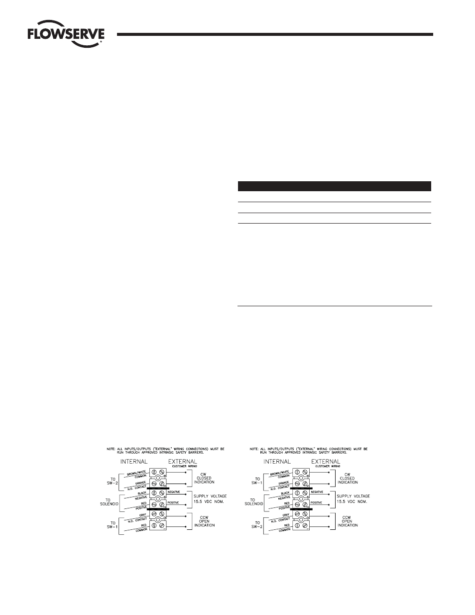
Make electrical connections in accordance with the
appropriate wiring diagram on inside of cover or the
appropriate diagram in figure 3:
NOTE 2: Installation of Intrinsically Safe Systems is to be done
in accordance with Canadian Electrical Code, Part 1 and
National Electrical Code, Chapter 1.
DEFINITIONS:
Ca-Maximum Allowed Capacitance
Li-Maximum Internal Inductance
Ci-Maximum Internal Capacitance
Voc-Maximum Output Voltage
I max-Maximum Input Current
V max-Maximum Input Voltage
Isc-Maximum Output Current
Vt-Voltage Total
La-Maximum Allowed Inductance
Flow Control
Worcester Controls
Figure 3
FAIL-CLOSED
(Sizes 10–40 in-line operation)
(Sizes 25–40 cross-line operation)
FAIL-OPEN
(Sizes 10–20 in-line, inverted operation)