0 troubleshooting, Worcester controls – Flowserve Worcester Controls Electri-SAFE DataFlo User Manual
Page 19
FCD WCAIM2048-01
Electri-SAFE DataFlo Digital Electronic Positioner
19
Flow Control
Worcester Controls
b. Route the wires neatly and use wire ties if necessary. Be
certain that the wires will not get fouled on the shaft when it
rotates.
6.4 Operation
a. Once the positioner unit has been assembled and connected
to the actuator, the switch cams can be set per user’s
requirements. Normally switch 2 indicates closed and
switch 3 indicates open.
b. The unit should be operated to ensure that switch actuation
occurs at the end of rotation (or in whatever position is
desired by the customer) repeatably.
6.5 Troubleshooting
7.0 Troubleshooting
If the Electri-SAFE unit does not operate, the first thing to do is to
determine if the problem is with the actuator or the positioner per
flow chart on the next page.
7.1 General
7.1.1 Check the Input Signal Fuse F1. Location of the fuse is
shown on the circuit board (see figure 1 in the appendix).
Check fuse F1 to see if it is blown. If it is, replace it with
Littlefuse PICO II very fast-acting fuse rated at 62 mA.
(Newark part number 94F2146).
IMPORTANT: To check fuse F1, remove it from circuit and test
with ohmmeter. Resistance should be about 6 ohms.
NOTE: If fuse F1 is blown, excessive voltage (possibly 120
VAC) was applied to the signal input circuit. If so, correct this
condition before changing fuse.
7.1.2 Signal Noise
If the circuit board’s LEDs blink or seem to continuously glow,
electrical noise is interfering with the positioner’s input
process signal. Always use shielded cable for the process
signal coming to the digital positioner terminal strip. Ground
the shield at one end only.
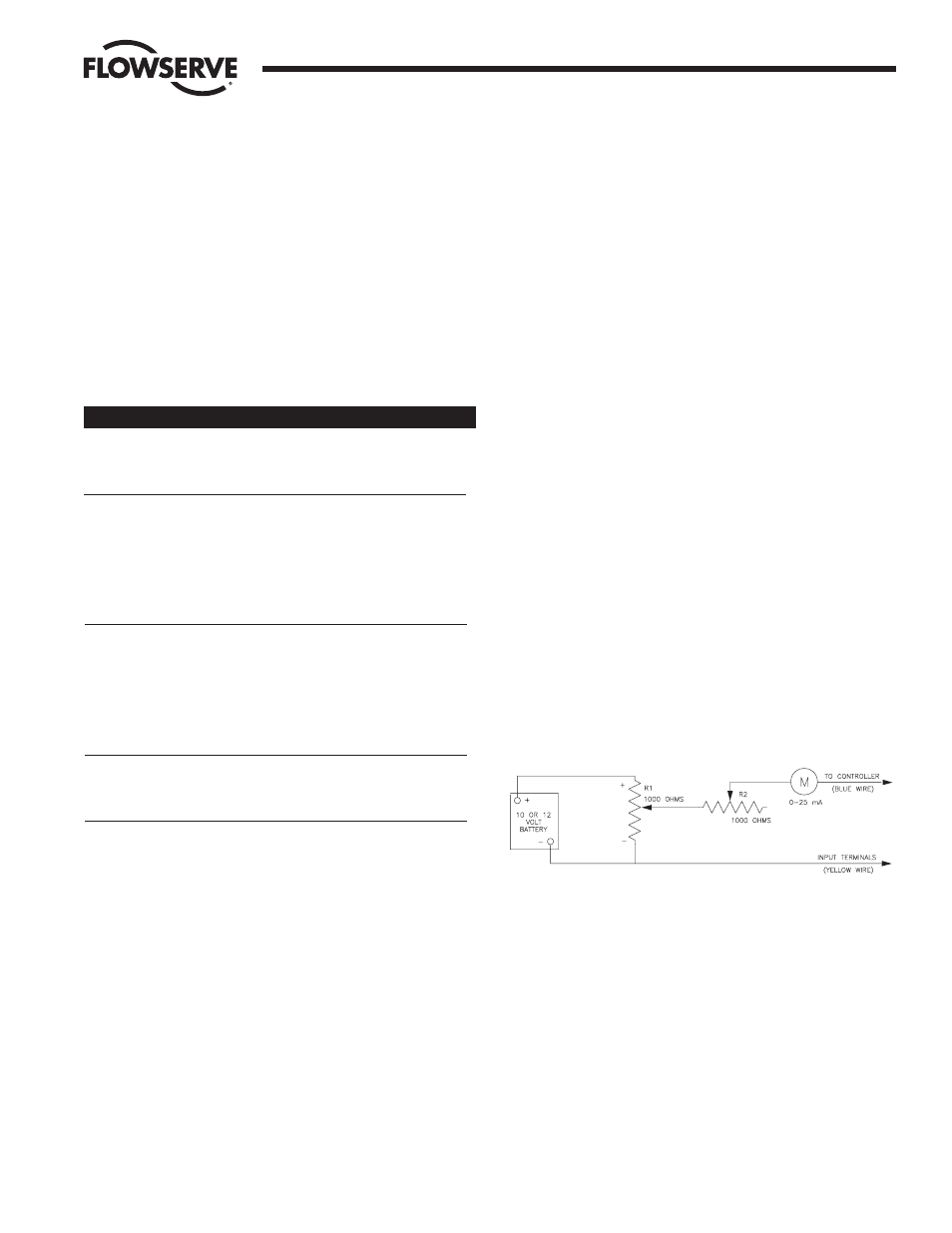
7.1.3 Signal Generator
To facilitate troubleshooting a positioner, it would be
advantageous on resistive input units to connect a
potentiometer directly to the signal input terminals in place of
the standard process input. Use a 135 ohm or 1000 ohm
potentiometer depending on which model is used. Figure 6
below shows a schematic of a simple test unit that can be
connected to the input terminals to simulate the process
signal for a milliamp input positioner.
Test Unit for milliamp Input Positioner – Set R1 all the way
toward the plus end. Adjust R2 for a 20 mA reading. Varying
R1 will now provide input signals between 4 and 20 milliamps.
7.2 Power Supply
7.2.1 General
The power supply is a separately enclosed metal housing that
contains the electronic components that supply the 5 volt logic
for the positioner board. It also houses the triacs that operate
the pump motor and positioning solenoid and CW/CCW
indicating LEDs. There are no fuses in the power supply.
7.2.2 Power Supply Output Voltage (5 VDC)
Check: (troubleshooting chart step 4)
Problem
Switches do not
indicate at proper
positions
Switch does not
actuate (never trips)
Switch does not
reset (always
tripped)
No indication at
terminal strip
Cams not aligned
with switch arms
Possible Causes
Improper cam
settings
Switch too far
from cam
Switch too close
to cam
Broken, defective,
or misplaced wire
Cams/spacers
in wrong order
Cams not pushed
into place
Solution
Reset cams.
Loosen the
adjustment plate
screws and rotate
switches toward
shaft until actuation
is correct. Retighten
screws.
Loosen the
adjustment plate
screws and rotate
switches toward
shaft until actuation
is correct. Retighten
screws.
Check wiring with
appropriate wiring
diagram in Appendix.
Check and
reassemble cams
per Part 6.2.
Push cams into
proper locations.
Align with switch
arms.
Figure 6