Worcester controls – Flowserve Worcester Controls Electri-SAFE DataFlo User Manual
Page 18
18
Electri-SAFE DataFlo Digital Electronic Positioner
FCD WCAIM2048-01
Flow Control
Worcester Controls
Switch
Common
N.O.
2
Red
Blue
3
Brown/White
Orange
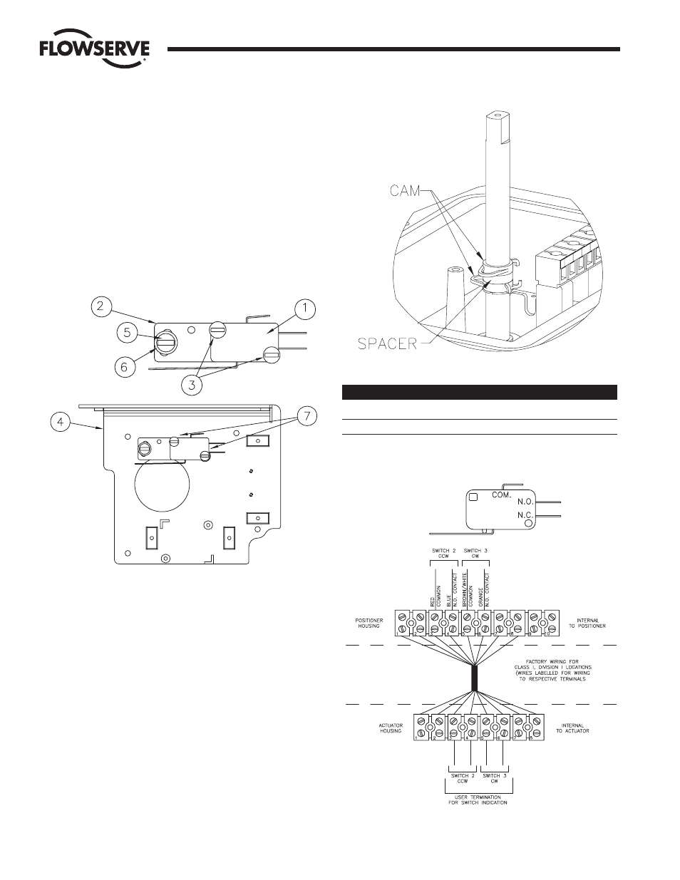
6.1 Assembly
a. M2 – TWO SPDT MECHANICAL SWITCHES
1. Stack two switches (item 1) and attach to the adjustment
plate (item 2), as shown in Figure 4, using two #4-40 x 1"
screws (item 3) provided. Note: One of the screws will
thread into a tapped hole in the adjustment plate while
the other engages a clearance hole without threads.
2. Assemble the switches and adjustment plate to the base
plate (item 4) as shown below, using the “loose” #4-40 x
1" screw and the #4-40 x
3
/
8
" screw (item 5) and #4
washer (item 6). Move the adjustment plate to a middle
position and tighten the screws.
6.2 Cams
Assemble the first spring cam, the spacer and second spring
cam. To work the spring cam down the shaft, squeeze the two
protrusions and turn. See Figure 5.
6.3 Wiring
NOTE: All wiring is to be run neatly and away from any rotating parts,
using wire ties, if necessary. Use caution to avoid pinching wires
between the base and cover flanges. All wiring to terminal strip
should be inserted only to midpoint of terminal strip.
a. The wire leads will be connected to the switches as
provided. Pay close attention to the switch labels,
schematics, wire colors, etc. when wiring the switches.
Switches are to be wired to the terminal strip as shown in
wiring diagram to the right.
Figure 4
Figure 5
Figure 6