Exploded view of spring diaphragm rotary actuator – Flowserve Spring Diaphragm Rotary Actuators User Manual
Page 9
9
Spring Diaphragm Rotary Actuators FCD VLAIM050-01 – 05/12
flowserve.com
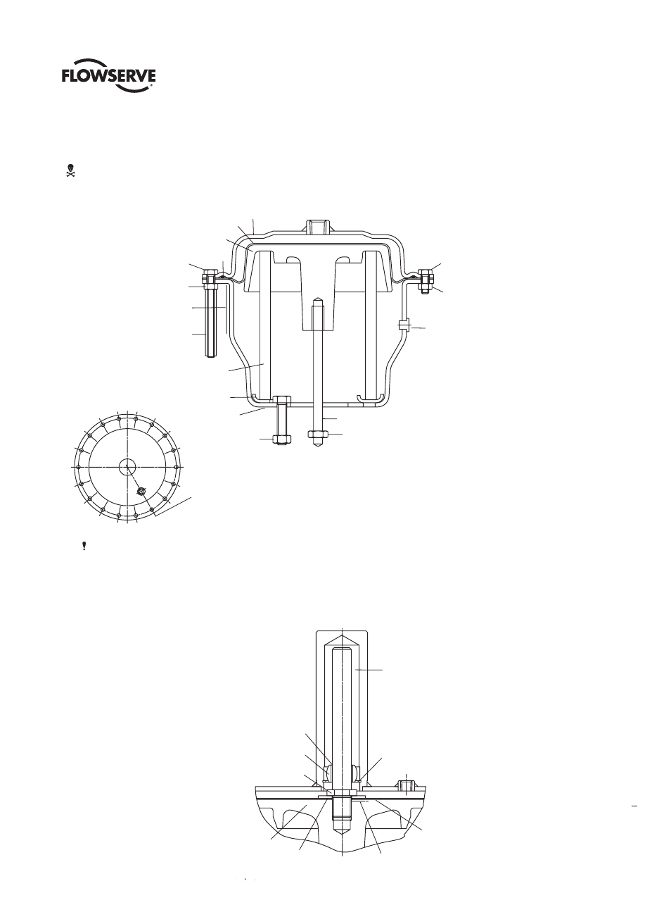
NOTE:
1. Item numbers correspond directly to the bill
of materials; refer to it for specific numbers.
2. NR2 guided designs are only used in high
cycle applications
3. NR3 guided designs are standard with
spring set valves of 1.4 to 2.8 bar (20 to 41
psi) or 1.9 to 3.8 bar (28 to 55 psi).
Item # Description
202a Upper Diaphragm Case
203 Lower Diaphragm Case
211 Actuator Stem
224 O-ring Seal
225 Diaphragm
227 Piston Diaphragm
229 Spring
256 Nut M8
326 Spring Guide
333 Plastic Tube Protection
334 Bolt M6
335 Bolt M6 X 16
350 Nut M6
351 Nut M6
435 Sticker
436 Plug Rubber
365 Clevis Nut
Kit 500 Guided Diaphragm Assembly
440 Guided Stem
441 Guide Cap
442 Bearing
443 Ret Ring Snap
444 Washer
445 Locknut
Locate the orientation of the pneumatic
connection on the center of this hole
KIT #500
Guided Diaphragm Assembly
(See Notes 2 and 3
)
442
441
445
227
444
440
443
225
Check seal in this area
after joining parts
WARNING: Use a press to unload spring, or lubricate the (3)
spring compression bolts (334) to unload spring.
Exploded View of Spring Diaphragm Rotary Actuator
Figure 4
256
335
202
225
227
224
334
350
435
333
229
326
203
365
211
436
351
256