Flowserve WG Series Limitorque User Manual
Page 13
13
Limitorque WG Series Worm Gear Operator FCD LMENIM2101-02 – 1/15
flowserve.com
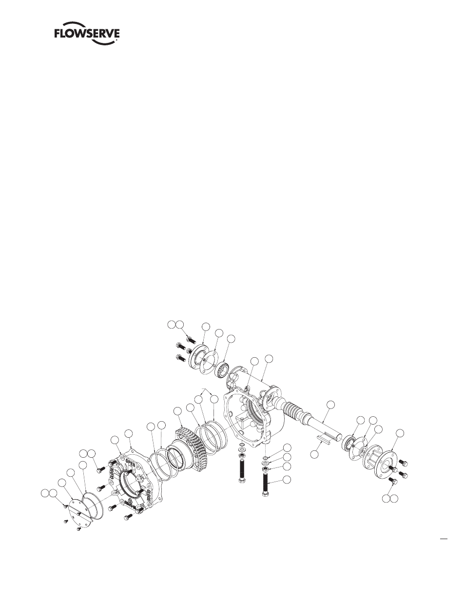
6. Install the End Cap (pc# 6) and Gasket (pc# 22).
7. Insert the Worm Shaft (pc# 3) into the Housing bore.
8. Install the Tapered Roller Bearing (pc# 11) onto the Worm Shaft in the Housing bore.
9. Replace the Oil Seal (pc# 19) in the Input Flange (pc# 7), if required.
10. Install the Input Flange (pc# 7) with Gasket (pc# 22) or install the Spur Gear Attachment (See Section 4.5 or 4.6).
Note:
Lubricate the worm gear mesh to replace lubricant lost during disassembly
(see Lubrication, Section 3).
11. Place the upper Thrust Washer (pc# 9) on the Worm Gear/Drive Sleeve (pc# 5).
12. Replace the upper O-Ring (pc# 20) in the Housing Cover (pc# 2).
Note:
Lubricate all O-Rings before installation.
13. Install the Housing Cover (pc# 2) with Cover Gasket (pc# 21).
14. Replace the upper O-Ring (pc# 18) in the Housing Cover (pc# 2).
15. Replace the Pointer Cap O-ring (pc# 31) in the top of the Worm Gear/Drive Sleeve (pc# 5).
Note:
Lubricate all O-Rings before installation.
16. Install the Pointer Cap (pc# 8).
17. Turn the operator upside
down and insert the Splined
Adapter (pc# 4).
18. Install the Splined Adapter
Retaining Ring (pc# 10).
4
29 14
30 12
28 13
8
31
18
2
21
20
9
5
9
6
22
11
24
1
3
32
23
16
15
27
13
28
11
22
19
7
17
17
10
(VARIES)
PC-7 IS REPLACED BY
OPTIONAL SPUR GEAR
ATTACHMENT, IF SUPPLIED
Figure 4.2 –
WG-00 through WG-35 Exploded View