2 safety practices – Flowserve WG Series Limitorque User Manual
Page 12
Limitorque WG Series Worm Gear Operator FCD LMENIM2101-02 – 01/15
12
4.2 Safety Practices
The following checkpoints should be performed to maintain safe operation of the WG gear operator:
• Set up a periodic operating schedule on infrequently used valves.
• Ensure that the limit and/or torque switches on any electric actuator fitted to the WG worm gear operator are
correctly and appropriately adjusted.
4.3 WG-00 Through WG-35
Refer to Figures 4.1 through 4.6.
Disassembly Instructions:
1. Place the operator upside down to access the mounting base.
2. Remove Retaining Ring (pc# 10) and Splined Adapter (pc# 4).
3. Return the operator to the upright position (mounting base down) and remove the Hex Head
Cap Screws (pc# 14), Pointer Cap (pc# 8) and O-rings (pc# 18 & 31).
4. Remove the Hex Head Cap Screws (pc# 12), Housing Cover (pc# 2) and Cover Gasket (pc# 21).
5. Remove the Input Flange (pc# 7), with Oil Seal (pc# 19) and Gasket (pc# 22), or remove the Spur Gear
Attachment (See Section 4.5 or 4.6).
6. Remove Worm Shaft (pc# 3) with Tapered Roller Bearing (pc# 11) from the Housing (pc# 1).
7. Remove the Tapered Roller Bearing (pc# 11) from the Worm Shaft (pc# 3), if required.
8. Remove the End Cap (pc# 6) and Gasket (pc# 22).
9. Remove the Tapered Roller Bearing (pc# 11).
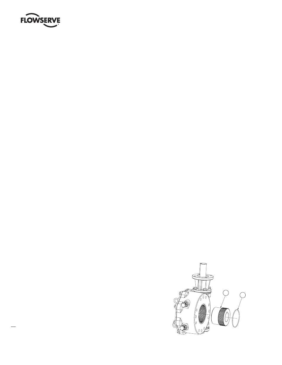
10. Remove the Worm Gear/Drive Sleeve (pc# 5), O-Rings (pc# 17), and Thrust Washers (pc# 9).
11. Remove the Stop Screws (pc# 15) with Hex Nuts (pc# 16), Packing Seals (pc# 23) and O-rings (pc# 32).
Reassembly Instructions:
1. Install the Stop Screws (pc#15), including the O-Rings (pc# 32),
Packing Seals (pc# 23) and Hex Nuts (pc# 16).
2. Place the lower Thrust Washer (pc# 9) in the Housing (pc# 1).
3. Replace the lower O-Rings (pc# 17) in the base of the
Housing (pc# 1).
Note: Lubricate all O-Rings before installation
.
4. Install the Worm Gear/Drive Sleeve (pc# 5).
5. Install the Tapered Roller Bearing (pc# 11) into the
Housing bore on the End Cap side.
4
29
14
30
12
28
13
8
31
18
2
21
20
9
5
9
6
22
11
24
1
3
32
23
16
15
27
13
28
11
22
19
7
17
17
10
(VARIES)
PC-7 IS REPLACED BY
OPTIONAL SPUR GEAR
ATT
ACHMENT
, IF SUPPLIED
Figure 4.1 – Splined Adapter Assembly