Flowserve Modutronic 20 II Modulating Position Controlle User Manual
Page 14
Limitorque Actuation Systems Modutronic 20 II FCD LMENIM4002-00 – 08/06
14
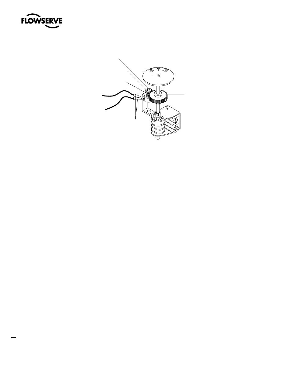
Figure 4.3 – Potentiometer Calibration Components Shown on a LY Position Indicator
5. If the reading is not correct, proceed to Step 6. If the reading is correct proceed to Step 7.
6.
a. Loosen the small Set Screw that retains the Potentiometer Drive Spur Gear to the
Potentiometer Shaft.
b. Remove the Spur Gear to allow manual rotation of the Potentiometer Shaft.
c. Rotate the Potentiometer Shaft until the correct readings are obtained as described in
Step 4.
d. Reposition the Spur Gear to re-engage with the Gear Train.
e. Proceed to Step 7.
7. Disconnect the ohmmeter and reconnect the Potentiometer wiring to original connection.
4.4 Connecting the Mod 20 II
to Customer Command Signal Leads
WARNING: Hazardous Voltage. Turn power OFF before removing the actuator cover and
connecting the command signal.
If the Mod 20 II was factory installed, the only connection required is the user input command signal
leads (normally 4-20 mA). These connections should be made at the terminal strip in accordance
with the wiring diagram enclosed with the actuator.
NOTE: if the unit does not have factory-supplied pushbuttons, refer to your wiring diagram to install a
customer-supplied pushbutton station.
If retrofitting or adding a Mod 20 II to an existing actuator, use the following connection table and
your wiring diagram for wire lead designations.
c
Potentiometer
Shaft
Spur Gear
Setscrew
End
Connection
Center
Connection
Ohmmeter
to Pot Leads
Potentiometer
Drive Gear
50 100
0
PERCENT OPEN
Limitorque
Potentiometer
Shaft
Spur Gear
Setscrew
End
Connection
Center
Connection
Ohmmeter
to Pot Leads
Potentiometer
Drive Gear
50 100
0
PERCENT OPEN
Limitorque