Flowserve Modutronic 20 II Modulating Position Controlle User Manual
Page 12
Limitorque Actuation Systems Modutronic 20 II FCD LMENIM4002-00 – 08/06
12
Single-Phase Motor
1. Using the Handwheel, move the valve to a midtravel position (midtravel position allows electrical
operation in the valve “safe” area and keeps the OPEN and CLOSED limit switches from tripping
while testing motor direction).
2. Test motor direction by momentarily pressing the OPEN pushbutton:
a. If the actuator moves toward CLOSED, immediately turn power OFF and proceed with the
following instructions that match your application.
1. Permanent Split Capacitor single-phase motors can be connected for opposite rotation
by interchanging the leads T1 and T2 coming from the motor to the terminal strip.
2. Single-voltage, capacitor-start, induction-run, single-phase motors interchange leads T2
and T3 coming from the motor to the terminal strip.
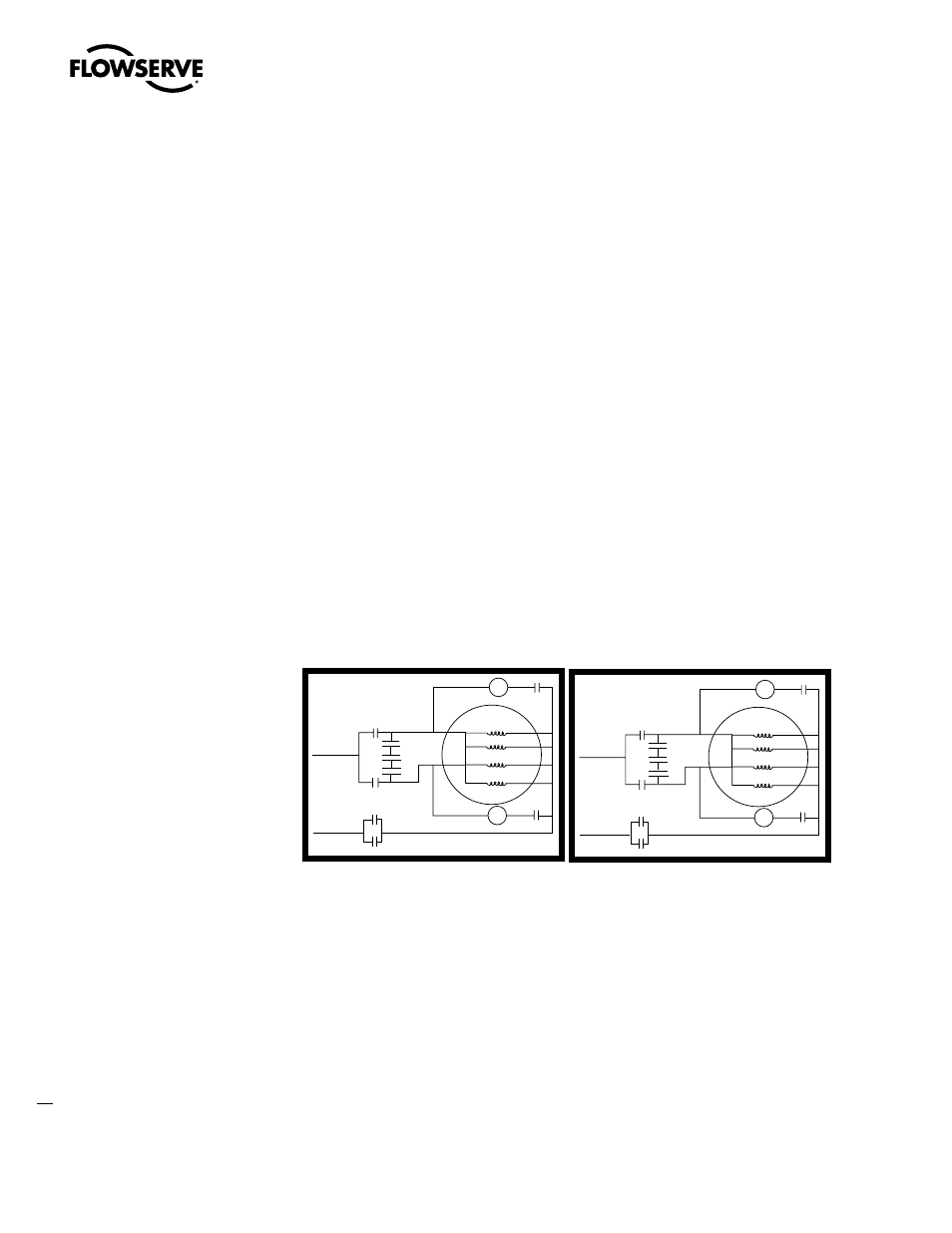
3. Dual-voltage, capacitor-start, induction-run, single-phase motors can be connected for
opposite rotation but the connection depends on whether the motor is operated on low
voltage or operated on high voltage.
Low-voltage motors are connected for opposite rotation as shown in the changes
between the Standard Rotation configuration and the Reverse Rotation configuration
in Figure 4.1. This is accomplished by interchanging the two leads T1 and T3 coming
from the motor with the two leads T6 and T8 also coming from the motor. No other
changes are necessary.
Figure 4.1 – Standard Motor Rotation and Reverse Motor Rotation Wiring Diagrams for Dual-Voltage,
Capacitor-Start, Induction-Run, and Single-Phase Low-Voltage Motors
High-voltage motors are connected for opposite rotation as shown in the changes
between the Standard Rotation configuration and the Reverse Rotation configuration
in Figure 4.2. This is accomplished by interchanging two set of leads. First, interchange
the leads T1 and T8 coming from the motor. Second, interchange leads T3 and T6 at
the starting relays R1 and R2. No other changes are necessary.
•
•
Standard Rotation
Wiring
T6
T3
L1
L2
4
C
5
R2 T7
O
C
R1
R2
Cap
1
2
1
2
O
C
R1
T5
4
5
O
T6
T9
T10
T3
T1
T4
T8
T2
Reverse Rotation
Wiring
T6
T3
L1
L2
4
C
5
R2 T7
O
C
R1
R2
Cap
1
2
1
2
O
C
R1
T5
4
5
O
T8
T4
T2
T6
T8
T9
T1
T10
Standard Rotation
Wiring
T6
T3
L1
L2
4
C
5
R2 T7
O
C
R1
R2
Cap
1
2
1
2
O
C
R1
T5
4
5
O
T6
T9
T10
T3
T1
T4
T8
T2
Reverse Rotation
Wiring
T6
T3
L1
L2
4
C
5
R2 T7
O
C
R1
R2
Cap
1
2
1
2
O
C
R1
T5
4
5
O
T8
T4
T2
T6
T8
T9
T1
T10