Flowserve G4 Marathon Sleeveline Plug Valves User Manual
Page 15
15
8. The Grafoil packing ring (Part 20) is placed over the stem
(Figure VI-5).
9. Using the diaphragm guide P/N BY86272A to protect the
o-ring from the stem edge, install the first o-ring by
“rolling” it with your fingers over the guide and into the
lower stem groove (Figure VI-6). Install Teflon split ring in
a similar manner such that it is located above the o-ring
inside the lower groove. See Figure VI-7.
10. Install second o-ring and split ring in upper groove in a
similar manner, except that the diaphragm guide should
be raised by hand so that the lower edge of the guide
does not contact the lower o-ring assembly. See Figure
VI-7. Coat both o-ring assemblies liberally with Krytox
grease.
11. Place the thrust collar/diaphragm over the plug stem and
gently maneuver it over the o-rings onto the Grafoil ring.
The thrust collar (Part 11) is then driven into place
through the use of the thrust collar guide part # series
BY86273A and arbor press (Figure VI-8).
12. The Grafoil top cap gasket (Part 21) is to be installed with
the tapered or small edge diameter down or placed
against the valve counterbore. The plug is pushed down
until it is flush with the bottom of the body port in order
to check the diaphragm fit inside the Grafoil gasket for
clearance. The PFA diaphragm must not ride on the
Grafoil gasket but should fit just inside the Grafoil.
13. The adjuster fasteners must be preset per Section VB-6.
Check that the inner diameter of the gasket pad of the top
cap has between a 1/16" x 45° to 3/32" x 45° chamfer. If
not, remachine the top cap to this dimension. The top cap
(bonnet) (Part 3) and thrust collar assembly is installed
and the plug is pushed down in the open position again
until the bottom of the port is flush and the top cap
bottoms firmly on body counterbore. The top cap must
be checked before installation to ensure there is no
chamfer on outside edge of the cap.
14. The top cap is visually located to be evenly spaced inside
the body counterbore. The side of the top cap compres-
sion flange is equally spaced with the side wall of the
body counterbore. Fasteners should be installed and
tightened to 5 ft-lb torque to prevent movement of the
cap during initial torquing. Push down on the top cap
evenly until the top cap gasket pad seats firmly against
the body counterbore.
15. Once it has been determined that the gaskets fit properly,
continue to tighten the top cap fasteners in 50 ft-lb incre-
ments in a crisscross fashion to the levels found in Table
#1a & 1b, page 12.
Note: All fastening torques are for Locktite
®
coated,
corrosion free fasteners and nuts. Extreme care must be
taken to prevent overstressing fasteners and subsequent
valve parts by tightening in excess of industry standards
for appropriate size and alloy fasteners. Ref. Torque Table
#1a & 1b.
16. The adjuster fasteners (Part 12A) are loosened and the
plug is turned a minimum of three times. The sleeve is
checked on all four seal zones for tears.
17. With the plug in the open position, adjuster fasteners
(Part 12A) are then torqued to the following levels or until
the plug port is 1/6" above or flush with body port: Ref.
Table #2, page 12.
Size
Torque
6"
180 in-lb
8"
372 in-lb
8N
480 in-lb
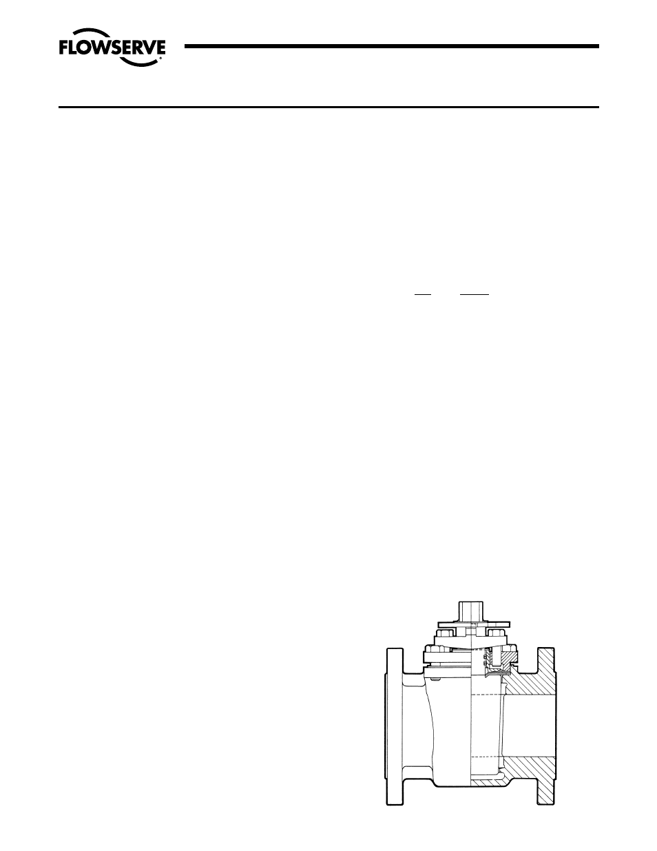
18. Operate the plug a minimum of three times. The valve
should look similar to Figure VI-10.
19. The gear box or actuator is installed with the plug set in
the open position and the open position adjusting screw
of the gear is then locked. Careful attention is required to
set the gear box stop screw at 90° rotation for the closed
position. A protractor may be used to check for 90°
rotation or alignment scribes may be noted on the gear
box cover.
20. LEAK TESTING: Anytime a valve has been modified in
any manner, including fastener changes, it should be
retested. Normal testing using gas, should be at 150 PSI
for Class 150 and 300 PSI for Class 300 valves from
1
/
2
" through 6". It should be noted, however, that this test
does not meet the requirements of ANSI, API or MSS.
For test procedures complying with these specifications,
refer to the appropriate published specification or
contact Flowserve.
SECTION VI
ASSEMBLY SPECIFICATIONS – FIRESAFE VALVES G4Z, G4ZHF, G4ZR
Flow Control Division
Section 1.0
FIGURE VI-10
ASSEMBLED G4Z MARATHON & G4ZHF MARATHON