Flowserve G4 Marathon Sleeveline Plug Valves User Manual
Page 14
14
Flow Control Division
Section 1.0
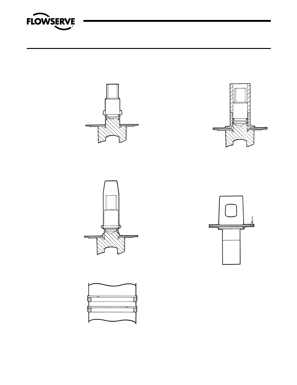
(Figure VI-6). Install
Teflon split ring in a
similar manner such
that it is located above
the o-ring inside the
lower groove. See
Figure VI-7.
10. Install second o-ring
and split ring in upper
groove in a similar
manner, except that the
diaphragm guide
should be raised by
hand so that the lower
edge of the guide does
not contact the lower
o-ring assembly. See
Figure VI-7. Coat both
o-ring assemblies
liberally with Krytox
®
grease. Remove the
guide.
11. Place the thrust collar/
diaphragm over the
plug stem and gently
maneuver it over the
o-rings onto the Grafoil
ring. The thrust collar
(Part 11) is driven into
place through the use
of the thrust collar
guide, part series
#BY86273A, and arbor
press (Figure VI-8).
12. The entire assembly
is turned over and the
Grafoil gasket placed on
the metal diaphragm
(Figure VI-9). A small
amount of rubber
cement is placed on the
Grafoil in several places
to cause it to adhere to
the metal diaphragm.
13. Continue to assemble
the valve per Step 9 of
Section V A for the
1
/
2
"-
3
/
4
" size valves or Step
11 in Section V B for
the 1"-4".
6"-8"-8"N
Due to the tooling and
associated equipment
required (presses, fix-
tures, etc.) to handle 10"-
14" size valves, it is high-
ly recommended they be
returned to the factory
for repair and rebuild.
1. Normal procedures
for field replacement
of one piece sleeves
are to be followed
for inserting the
sleeve Section V B,
steps 1-4.
2. The firesafe top seal
assembly differs
from the standard
G4 top seal and is
completed per the
following instruc-
tions.
3. The PFA diaphragm
(Part 6) is to be
flared on the
diaphragm guide
just enough to slip
over the plug stem
(Figure VI-1).
4. The plug stem and
diaphragm guide
should be checked
for nicks before
installing the PFA
diaphragm. Nicks on
this surface could
result in scratches on the lip of the diaphragm. The PFA
diaphragm is placed over the diaphragm guide with the
lip down (Figure VI-2). Remove the guide.
5. The thrust collar (Part 11) and thrust collar guide, part
series #BY86273A, are to be installed over the plug stem
and loaded by an arbor press to flatten the PFA firesafe
diaphragm. Remove the thrust collar and thrust collar
guide.
6. The metal diaphragm (Part 6A) is placed over the plug
stem and the hole enlarged just enough to slip down on
the stem (Figure VI-3).
7. A thin coat of silicone oil is applied to the down edge of
the metal diaphragm. The diaphragm is then placed over
the plug stem with the lip down (Figure VI-4).
SECTION VI
ASSEMBLY SPECIFICATIONS – FIRESAFE VALVES G4Z, G4ZHF, G4ZR
FIGURE VI-5
Grafoil packing ring placed
over stem.
FIGURE VI-6
O-ring placed over stem.
FIGURE VI-7
FIGURE VI-8
Packing and thrust collar driven
into place.
GASKET
FIGURE VI-9
Grafoil gasket placed on metal
diaphragm using a bonding material.