Flowserve Valtek StarPac 1 Intelligent Control Systems User Manual
Page 4
41-4
Flowserve Corporation, Valtek Control Products, Tel. USA 801 489 8611
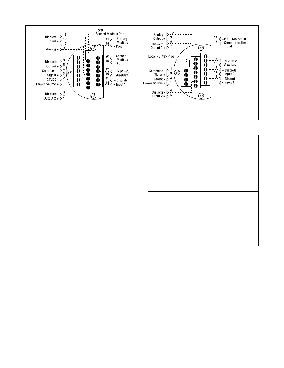
Signal
Positive Negative
Term.No. Term.No.
24 VDC power
1
2
Valve command signal
3
4
Primary RS-485
11
18
communication link (Port A)
RS-485 communication
19
20
link (second / Port B)
Auxiliary input (4 - 20 mA)
17
16
Analog output (4 - 20 mA)
9
10
Discrete input 1 – switch/
13
12
solenoid monitoring (discrete
mode source input)
Discrete input 2 – switch/
15
14
solenoid monitoring
Discrete output 1
5
6
(malfunction alarm contact)
Discrete output 2 (special)
7
8
WARNING: Do not remove the electronic
housing cover in flammable atmospheres;
otherwise possible injury to personnel or equip-
ment may occur.
2. Connect the required wires to the terminal interface
block and computer as described in Figure 3 and
Table I. (The system must have 24 VDC power and
signal cable for operation.)
NOTE: The StarPac system remembers the oper-
ating mode setting (automatic or manual) from the
last time the unit had power. When power to the
system is turned on again, the unit will resume
operation in the previous mode.
Normally the StarPac system arrives from the fac-
tory set in the manual operating mode. This means
a command signal will position the valve the same
as a conventional control valve, providing a plug
position proportional to the 4 - 20 mA signal.
To avoid upsetting the process because of im-
proper operating mode selection:
• Ensure that the system arrived from the factory with
the proper operating mode setting in the shop prior
to installation by connecting the air supply and
command signal, then turning on the power and
looking at the mode value on the local display, or;
• Set the proper operating mode for the particular
application in the shop prior to installation by select-
ing the desired operating mode from the Tuning/
Tune screen in the StarTalk software, or;
• Ensure that the block valves in the process line
around the StarPac system are closed and the
process is diverted around the unit.
3. Turn on the 24 VDC power to the unit, and verify that
the StarPac system has been correctly wired by
checking the following:
• 24 VDC power is at least 300 mA and between
21.6 and 27.0 VDC
Model SPJD, NT
Model SP, SPJS
Figure 3: User Interface Terminal Pinouts
• Polarity is correct
• Local display is on; if not, check the power supply
or reset switch
The StarPac local display should now be on, indi-
cating the following:
• Valve stem position
• Setpoint signal
• Process flow value (gas or liquid)
• Temperature of process
• Upstream (P
1
) and downstream (P
2
) pressures
At this point the StarPac unit is installed and will
operate as a conventional control valve receiving a
4 - 20 mA command signal from a DCS, or other
device, and stroking the valve accordingly.
Table I: User Interface Terminal Connections