Commissioning, Wiring – Flowserve NRG 16-11 User Manual
Page 17
7
Apply mains voltage to level switch NRS -7.
Commissioning
Check whether the NRG …- and the associated controller NRS -7 are wired in accordance with
the wiring diagram.
Fig. 14, Fig. 15
Check wiring
Apply mains voltage
Wiring
– continued –
Tools
■
Screwdriver for cross-recess head screws, size
■
Screwdriver for slotted screws, size .5, completely insulated according to DIN VDE 0680-
■
Open-end spanner A. F. 8 (9)
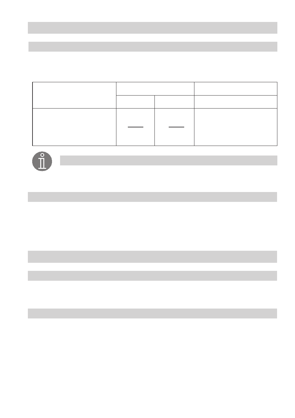
Voltage table
Use this voltage table as a reference when checking whether the level electrode is submerged or if
there is a malfunction. Please take the wiring diagram of the electrode NRS -7 into account.
Fig. 14, Fig. 15
Note
■
The self-checking routine of the amplifier NRS -7 reduces
U
-
every 40 seconds to
0 volt!
U
-
0 V
eff
0.5 µS/cm,
C=0.3 cm
-
V
eff
0 µS/cm,
C=0.3 cm
-
U
-
⊥
U
-
⊥
submerged
exposed
malfunction (submerged/alarm)
U
-
2
<
U
-
2
≥
U
-
⊥
≤