Flowserve Valtek MaxFlo 3 User Manual
Page 10
®
User Instructions - MaxFlo 3 - VLEEIM7001-03 07.07
0
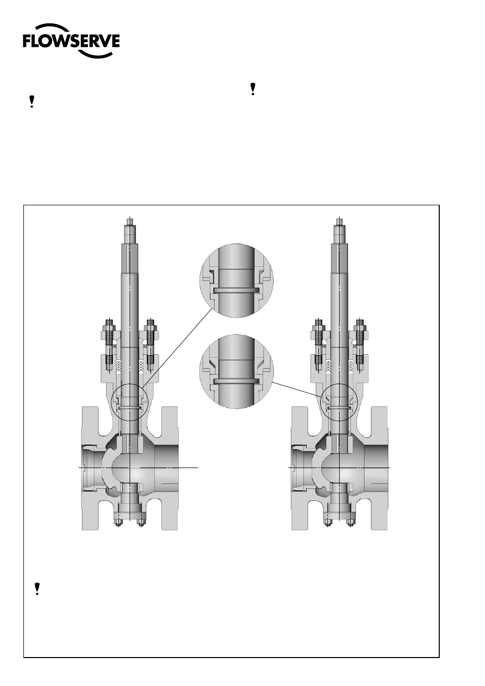
Figure 6a: old design
9. PRINCIPLES OF SHAFT ANTI-BLOWOUT SYSTEM
Figure 6b: new design
8
ACTUATOR REMOUNTING
NOTE: The MaxFlo 3 valve opens in a clockwise direc-
tion when looking down the valve shaft.
8.
When remounting the actuator to the valve, refer to the
appropriate actuator manual.
NOTE: The actuator stroke stops must be adjusted
correctly to avoid any over-rotation of the plug stroke.
Poor adjustment can cause damage to the valve. Pay
special attention to the adjustment of the closing stop
when the valve has a soft seat.
8.
Install the valve in the pipeline as indicated in the “In-
stallation” section according to the orientation recom-
mendations given at the end of the manual.
NOTE: The MaxFlo 3 valve has been significantly im-
proved, with even greater safety for the anti-blowout
system (see figure 6).
The diameter of the shaft shoulder exceeds the di-
ameter of the bonnet bore. Even if the thrust bearing
(item 46) is not installed during reassembly, the shaft
cannot pass through the bonnet.
It is possible to upgrade from the old design (prior to
mid-2006) by changing the bonnet (40) and the pack-
ing stop (99).
To order the correct replacement parts, contact your
Flowserve representative with the serial numbers
of the valves requiring the upgrade.