Operating level – Flowserve LRGT16-1 Spector compact Conductivity Transmitter System User Manual
Page 26
The displayed parameter values of SP 2, LCL, LCH, SdA 1, SPL, SPH, InL and InH
depend on the decimal point.
Specifications in % refer to the span I n L .... I n H.
First calibrate start and end of the control range (InL, InH) and then the upper and lower
set-point limits (SPL, SPH).
Conductivity
transmitter
Controller
Control range*
[
µS/cm at 25 °C]
I n L
S P L
I n H
S P H
20 20.0
100 100.0
200 200.0
500 500.0
1000 1000
2000 2000
6000 6000
0.5
12000
0.5
9999
If the equipment is used for conductivity limiting purposes set the limit contact low
(LCL1) to the predefined max. electrical conductivity value. When this limit is exceeded the
green LED for Alarm 1 lights up and relay output 3 opens the burner protection circuit. The
adjusted limit value can be retrieved at any time on the parameter level. Relay output 3
does not interlock automatically. The interlocking function must hence be implemented in
the follow-up circuit (burner protection circuit), which has to comply with the requirements
of DIN VDE 0116.
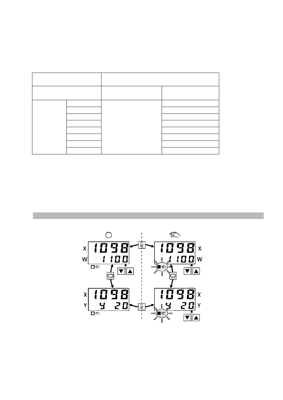
Operating Level
This level is for process control. Actual (process) value X and set-point W are displayed in
manual and automatic modes. Manipulated variable Y is displayed by means of selector
key. Manual and automatic modes are switched with Hand/automatic key.
26