Installation – Flowserve HV 215 User Manual
Page 25
25
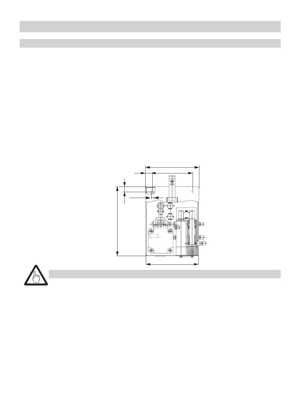
Operating device BV 110
Installation
– continued –
Fit the operating devices to both sides of the vessel such that they are easily accessible.
Each operating device consists of:
n
Hand lever
n
Adhesive label for valve position (no. 04856)
The operating devices are supplied completely mounted.
See drawing on page 4
. Weld or screw the operating devices
E to the frame W.
The body of the operating device
E is provided with two bore holes (diameter 3 mm) for screwed unions.
The associated screws and locking washers are not scope of the GESTRA supply.
Note that welding processes must be supervised by the local welding authority.
2. When you have finished welding and painting, stick the adhesive label
N indicating the valve position to
the back of the body behind the indicating piston
O.
Dimensions indicated in mm
Depth 64
Attention
The hand lever supplied by Gestra protrudes approx. 300 mm out of the rear wall of the body
when the flap is closed.
If necessary you can shorten the hand level by max.50 mm.
If the welding process has affected the coat of paint, make sure that the damaged paintwork
is repaired.
260
270
200
32
25
384
∅ 3