Figure 2: wiring diagram table 9: connection table – Flowserve 510si IOM Logix User Manual
Page 7
7
Compliance Voltage (Figure 9)
Output compliance voltage refers to the voltage limit the cur-
rent source can provide. A current loop system consists of
the current source, wiring resistance, barrier resistance (if
present), and the Logix 510 impedance. The Logix 510 re-
quires that the current loop system allow for a 6,0 VDC drop
across the positioner at maximum loop current.
CAUTION: Never connect a voltage source directly
across the positioner terminals. This could cause per-
manent circuit board damage.
In order to determine if the loop will support the Logix 510,
perform the following calculation:
Voltage = Compliance Voltage (@Current
MAX
)
- Current
MAX
*(R
barrier
+ R
wire
)
The calculated voltage must be greater than 6.0 VDC in order
to support the Logix 510.
Example:
DCS Compliance Voltage = 19 V
R
barrier
= 300 Ω
R
wire
= 25 Ω
CURRENT
MAX
= 20 mA
Voltage = 19 V - 0,020 A*(300 Ω + 25 Ω)
= 12,5 V
The voltage 12,5 V is greater than the required 6.0 V; there-
fore, this system will support the Logix 510si. The Logix 510si
has an input resistance equivalent to 300 Ω at a 20 mA input
current.
5.
Connect the outlet connector Y of the positioner
to the actuator with tubing, independent of the
action (direct or reverse).
7
WIRING AND GROUNDING GUIDELINES
Electrical connections: signal cable with cable pas-
sage (NPT, PG13,5, or M20 x 1,5) to terminals 2 x
2,5 mm
Input signal: 4 – 20 mA
NOTE:
Observe the minimum requirements of volt-
age and equivalent electrical load: 6,0 VDC / 300 Ω /
at 20 mA
The performance is ensured only for a minimum input cur-
rent of 3,6 mA.
For wiring, the following notes should be observed:
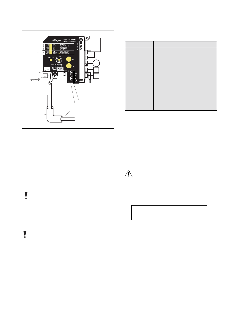
NOTE: The input loop current signal to the Logix 510si
should be in shielded cable. Shields must be tied to a
ground at only one end of the cable to provide a place
for environmental electrical noise to be removed from
the cable. In general, shield wire should be connected
at the source. (Figure 8)
Connect the 4-20 mA current source to terminals +11
and -12 (Figure 8).
Grounding Screw
The grounding screw, located inside the positioner cover,
should be used to provide the unit with an adequate and reli-
able earth ground reference. This ground should be tied to
the same ground as the electrical conduit. Additionally, the
electrical conduit should be earth grounded at both ends of
its run. The grounded screw must not be used to terminate
signal shield wires.
Figure 2: Wiring Diagram
Table 9: Connection Table
Connection
Description
+11
Input+ 4..20 mA
-12
Input- 4..20 mA
+31*
Output+ 4..20 mA
-31*
Output– 4..20 mA
+41*
Limit switch 1+
-42*
Limit switch 1-
+51*
Limit switch 2+
-52*
Limit switch 2-
Y
Pneumatic output signal (outlet)
Z
Air supply
* 0ptional
PIEZO
RELAY
POT.
LS1
LS2
Internal Housing
EARTH Terminal
Limit Switch 1
Limit Switch2
4-20 mA Signal
Connect Shield at Source Ground
-
+
4-20 mA Current Source
Shielded Cable
Y
Z