Flowserve 510si IOM Logix User Manual
Page 14
14
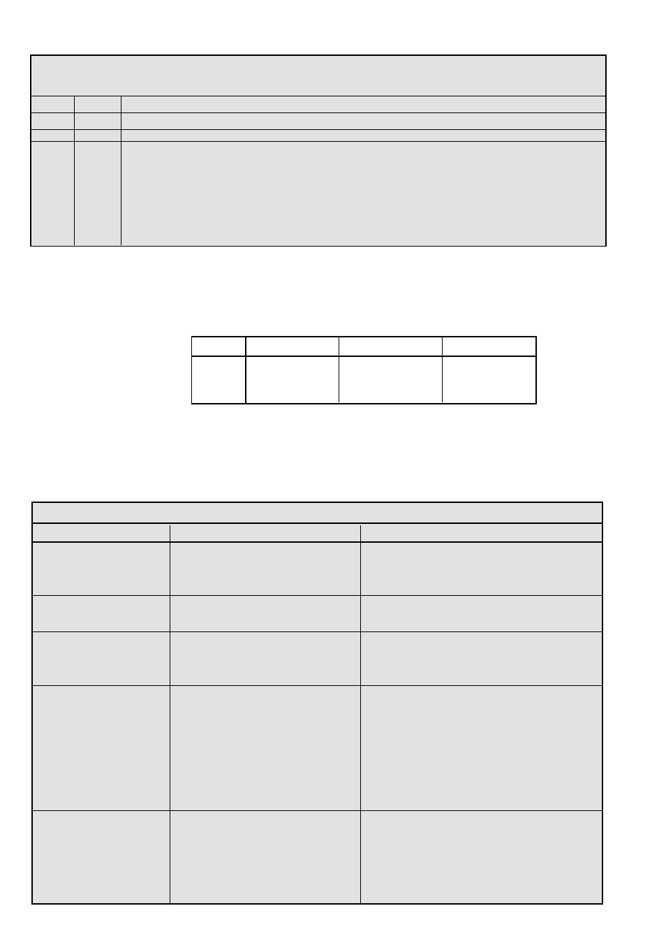
Troubleshooting Logix 510si Digital Positioners
Failure
Probable Cause
Corrective action
No LED is blinking
1. Current source below 3.6 mA
1. Verify current source is outputting at
least 3,6 mA
2. Incorrect wiring polarity
2. Check wiring for correct polarity
Unit does not respond
1.Error occurred during calibration
1. Correct calibration error. Recalibrate
to analog commands
Valve position reading is
1. Stroke not calibrated
1. Recalibrate
not what is expected
2. Stem position sensor mounting
2. 2.Orient sensor properly
is off 180 degrees
Position is driven fully
1. Stroke not calibrated
1. Calibrate valve stroke
open or closed and will
2. Inner-loop hall sensor not connected
2. Verify hardware connections
not respond to command
3. Wrong air action set on DIP switch
3. Check ATO (Air-to-open) and ATC
(Air-to-Close) settings. Recalibrate
4. Actuator tubing backward
4. Verify ATO/ATC actuator tubing
5. Electro-pneumatic converter
5. Replace electro-pneumatic converter
malfunctioning
Sticking or hunting
1. Contamination of the electro-
1. Check air supply for proper filtering
operation of the positioner
pneumatic converter.
and meeting ISA specifcations ISA-7.0.01
2. Control tuning parameters not
2. Lower gain switch settings
11 TROUBLE SHOOTING
Logix 510si Status Condition Codes
Colors Identifier
Indication and resolution
R - - -
Any sequence starting with a red light indicates that there is an operational problem with the unit.
RRYY
24
Bad electronic assembly - replace.
RGRR
25
Position Deviation – Indicates that he position has exceeded a fixed 20% error between command and
position for a period of time 5 times longer than the recorded stroke time. This error is usually seen when
the positioner is first mounted and powered up before a stroke calibration has been done. If the positioner
is properly calibrated, the air supply is correct, and the linkage is properly adjusted this error normally
indicates that there is a mechanical problem in the positioner, actuator, or valve that is preventing the valve
from stroking properly. If a regulated air supply connected to the actuator properly strokes the valve this
indicates a bad positioner and should be replaced if a calibration does not clear the error.
10
Version number checking- The version number of the embedded code may be checked at any time except during a
calibration by holding down the ∆ button. This will not alter the operation of the unit other than to change the blink
sequence to 3 blinks indicating the major version number. Holding the ∇ button will give the minor version number
without affecting operation. The version codes are interpreted by adding up the numbers assigned according to the
following table:
Color
First blink value
Second blink value Third blink value
Green
0
0
0
Yellow
9
3
1
Red
18
6
2
For example if holding the ∆ button gave a G-G-R code, and holding the ∇ button gave a Y-Y-G code then the resulting version number
would be (0+0+2).(9+3+0) or version 2.12.