7 additional electrical components, 1 reversing starter, 2 overload relays – Flowserve SMB Series Electric Actuators User Manual
Page 30
SMB Series/SB Series Installation and Maintenance FCD LMENIM1401-04-AQ – 01/15
30
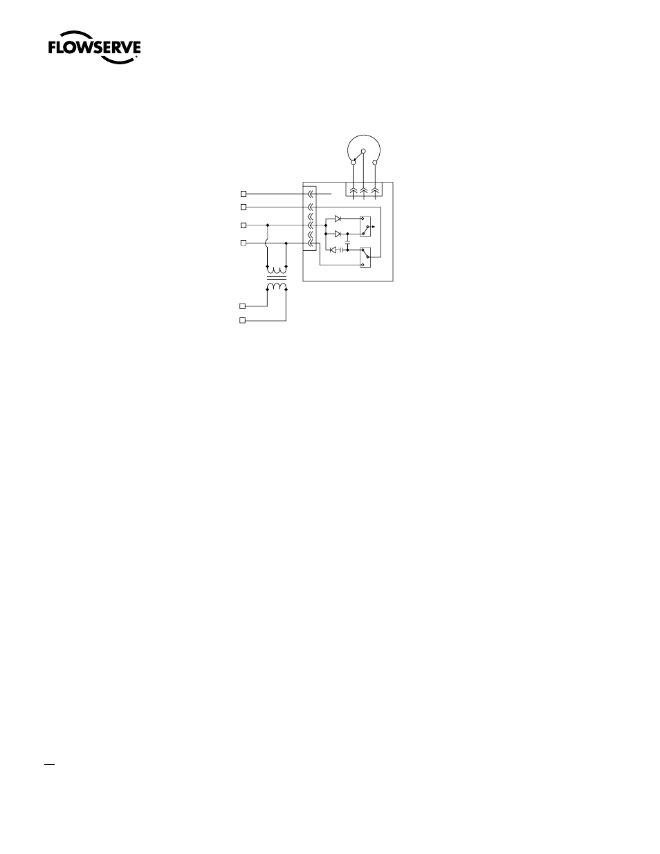
Figure 4.10 – Typical Connection for PT20SD R/I Converter
4.7 Additional Electrical Components
4.7.1 Reversing Starter
The reversing starter electrically changes the operation of the electric motor from one direction
of rotation to the other. The starter consists of two contactors mounted on a common base and
mechanically interlocked.
Each contactor consists of the following:
• three normally open power contacts
• one normally open circuit holding contact
• one normally closed interlock
• one magnetic holding coil.
The starter can be provided two ways:
• Mounted within the actuator limit switch compartment
• Supplied in a separate enclosure
4.7.2 Overload Relays
Overload relays de-energize the holding coils of the reversing starter, which open the power contacts
to de-energize the electric motor. The relays function at a predetermined current value and can reset
either automatically or manually as follows:
• Reset automatically if mounted as detailed in Figure 4.11.
• Reset manually if the reversing starter is furnished separately.
The relays are sized in accordance with full load (running) motor current.
4-20 mA
Output
Signal
(CW )
(S)
POT
1000 ohm
24 VDC or
18 VAC
See comments
under Section
4.6.3,
(+)
(–)
(+)
(–)
Black
Brown
Orange
Green
1
2
3
4
5
6
(+)m A
(–)m A
+V
18V
115V
BLU
BLU
Signal Converter
COM
AC
DC
LK3
1
3
2
1
3
2
CCW S C W
(CCW)
LK2
1 BLK
2 BRN
3 RED