4 setting the limit switch, 3 terminal connections, Ac b – Flowserve SMB Series Electric Actuators User Manual
Page 14
SMB Series/SB Series Installation and Maintenance FCD LMENIM1401-04-AQ – 01/15
14
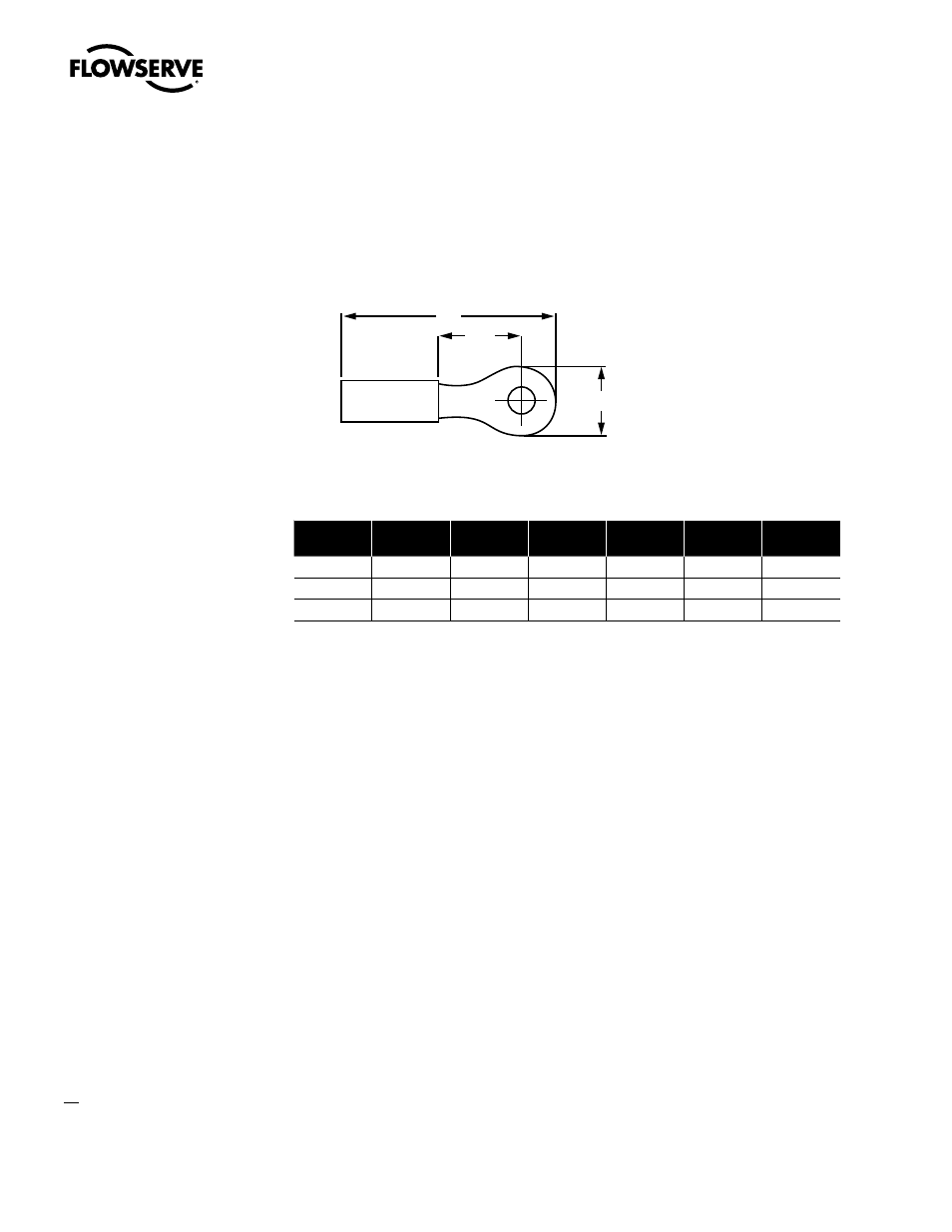
4.3.3 Terminal Connections
Wiring connections to the SMB geared limit switch, torque switch, and Marathon terminal strips are
to be made using ring-tongue terminals* as shown below:
Figure 4.1 – Wiring Connections
A
C
B
Table 4.3– Terminal Connections
AWG
Screw Hole
Insulation
Thomas &
Betts P/N
A
B
C
22-16
#10
Vinyl
18RA-10
.97
.31
.27
18-14
#10
Vinyl
14RB-10
.97
.31
.27
12-10
#10
Vinyl
14RC-10
1.06
.31
.27
Note: Limit switch and torque switch contacts are rated 300 volts per NEMA ICS-2
Terminals are to be crimped using Thomas & Betts crimping tool WT112M or ERG4001.
Manufacturer: *Thomas and Betts or equal
4.4 Setting The Limit Switch
c
WARNING: Disconnect all incoming power before opening or replacing the limit switch compart-
ment cover.
a
CAUTION: When wiring control circuits, distinguish between “normally open” and “normally
closed” terminals on the geared limit switch.
a
CAUTION: Do NOT attempt to repair the limit switch gear box. Replace entire limit switch gear
box.
a
CAUTION: Do NOT use abrasive cloth to clean the silver contacts on the limit switch. Contacts
should be burnished using appropriate burnishing tool.
a
CAUTION: Before motor operation, reset the geared limit switch if the actuator has been
dismantled or removed from the valve.
NOTE: Clean the limit switch cover thoroughly and apply a thin coat of grease on machined flange
surfaces before mounting on an explosion proof actuator.