Flowserve PMV D20 User Manual
Page 29
29
• Press and hold button while switching
on power to the D20, keep the button
pressed for 6 sec. The eeprom will now
be erased, and then all three LEDs are
lighted. The LEDs will start to flash
yellow-red. This starts FACTORY MODE!
To calibrate 4-20 mA input signal
• Apply 4.0 mA input signal and then push
the button three (3) times until all LEDs
are lighted. The LEDs will now start flash
yellow-red again.
Apply 20.0 mA input signal and then push
the button three (3) times until all LEDs
are lighted.
To calibrate 4-20 mA transmitter
output signal
Note! If no transmitter board is installed
the LEDs will start flash yellow-yellow and
the unit is ready for continued calibration.
If there is a transmitter board installed
the LEDs will start flash yellow-green.
The feedback transmitter output signal
on pin 9 and 10 will now follow the input
signal instead of the position. Apply 4.0
mA input signal. Measure the output sig-
nal and adjust the input signal up/down
until the output signal is 4.0 mA. Push
the button three times until all LEDs are
lighted. The unit will now start to flash
yellow-green again.
The output signal on pin 9 and 10 will
continue to follow the input signal instead
of the position. Apply 20.0 mA input sig-
nal. Measure the output signal and adjust
the input signal up/down until the output
signal is 20.0 mA. Push the button three
times until all LEDs are lighted.
The LEDs will start flash yellow-yellow
and the unit is ready for continued
calibration.
Press the button for 5 sec until the LEDs
start alternating, D20 starts to calibrate
stroke.
After calibration the unit will start running
in normal operation.
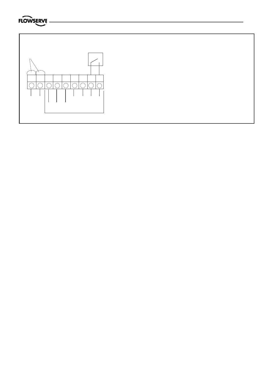
10.5 D20 Calibration of 4-20 mA input signal and/or 4-20mA
feedback transmitter
1
Input signal + 4-20 mA ,
Hart,
2
Input signal – 4-20 mA ,
Hart
3
Remote unit
4
Remote unit
5
Remote unit
9
4-20 mA + Feedback, 13-28 V DC
10
4-20 mA – Feedback, 13-28 V DC
11
Alarm output +, 8-28 V DC
12
Alarm output –, 8-28 V DC
HART-
connection
+ – + – + –
1
2
3
4
5 9 10 11 12
Remote unit
Option