Flowserve PMV D20 User Manual
Page 24
24
The PMV D20 digital positioner has been
designed to operate correctly in
electromagnetic (EM) fields found in
typical industrial environments. Care
should be taken to prevent the positio-
ner from being used in environments with
excessively high EM field strengths
(greater than 10 V/m). Portable EM
devices such as hand-held two-way ra-
dios should not be used within 30 cm of
the device.
Ensure proper wiring and shielding
techniques of the control lines, and route
control lines away from electro-magnetic
sources that may cause unwanted noise.
An electromagnetic line filter can be used
to further eliminate noise.
In the event of a severe electrostatic dis-
charge near the positioner, the device
should be inspected to ensure correct
operability. It may be necessary to
recalibrate the PMV D20 positioner to
restore operation.
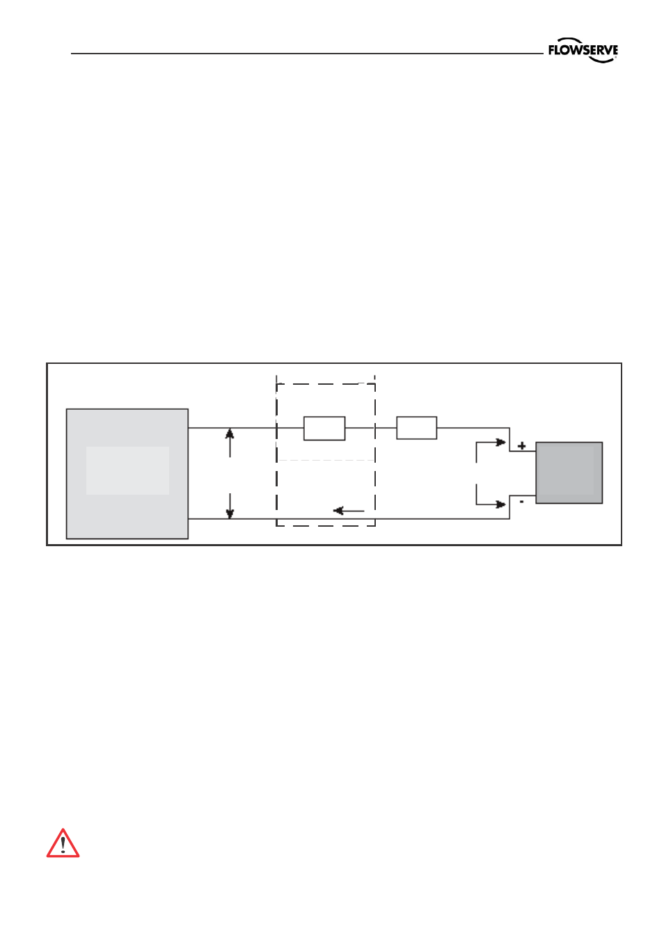
8.2 Electromagnetic compatibility
8.3 Compliance voltage
Output compliance voltage refers to the
voltage limit the current source can prov-
ide. A current loop system consists of the
current source, wiring resistance, barrier
resistance (if present), and the PMV D20
impedance.
The PMV D20 requires that the current
loop system allow for a 8.0 - 9.4 VDC
drop across the positioner at maximum
loop current.
CAUTION: Never connect a
voltage source directly across the
positioner terminals. This could
cause permanent circuit board
damage.
Figure 9. Compliance voltage
Current
Source
PMV
D20
Compliance
Voltage
If Present
R
R
Barrier
Wire
Current
In order to determine if the loop will sup-
port the PMV D20, perform the following
calculation:
Voltage = Compliance Voltage(@Current
MAX
)
– Current
MAX
(R
barrier
+ R
wire
)
To support the PMV D20 the calculated
voltage must be greater than 9.4 VDC for
D20 HART and 8 VDC for non-HART.
8 VDC