Flowserve 1400 Valtek Logix User Manual
Page 6
46-6
Flowserve Corporation, Valtek Control Products, Tel. USA 801 489 8611
16. Feed the driver module wires into the main chamber
of the housing and connect them to collector board.
17. Verify that the three O-rings are in the counter-bores
on the machined platform where the spool valve
block is to be placed (Figure 19)
18. Carefully slide the block over the spool, using the
machined surface of the housing base as a register
(Figure 5). Slide the block toward the driver module
until the two retaining holes line up with the threaded
holes in the base.
19. Install two spool-valve screws and tighten securely
with a phillips screwdriver.
20. Insert the orifice into the threaded hole in the driver
module assembly. Tighten with a
1
/
4
-inch open-end
wrench (Figure 4). Attach the flexible tubing from the
interface plate to this fitting.
21. Set the minimum pressure as described on page 10.
22. Thread driver module cover into driver module bore
in the main housing.
Spool Valve Cover
The spool valve cover incorporates a coalescing filter
element in a two-piece cover. This protects the spool
valve chamber from moisture and provides a low back
pressure vent for exhaust air from the spool valve.
Replacing Filter in Spool Valve Cover
1. Make sure valve is bypassed or in a safe condition.
2. Disconnect the power and air supply to the unit.
3. Remove the spool cover by removing the screw and
sliding the cover assembly backward until the tab is
clear of the slot. The sheet metal cover may be
removed and cleaned with a brush or by blowing out
with compressed air (Figure 7).
4. Remove the O-ring from around hydrophobic filter
element and set aside (Figure 6).
5. Remove the molded filter element by pulling it
straight out of chamber cover vent piece.
6. Install O-ring into base of chamber cover vent piece
as shown in Figure 6.
7. Place new molded filter element into the chamber
cover vent piece. This element provides part of the
track to secure the O-ring installed in the last step.
8. Place spool valve shroud onto spool valve cover.
9. Place the spool valve cover assembly in place by
setting it on the ramp and sliding it until the tab seats
in the slot (Figure 7) and secure with No. 8-32 screw.
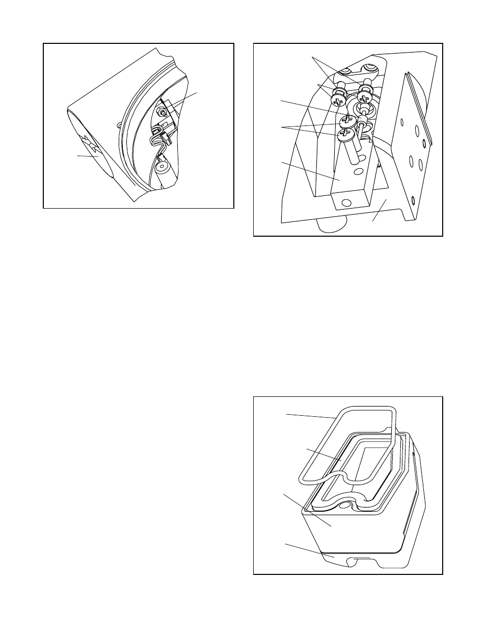
Figure 4: Driver Module Orifice
Orifice
Driver
Module
Cover
Figure 5: Spool and Block
Housing
Nylon Gaskets
Driver to
Housing Screws
Spool
Spool
Valve
Screws
Spool
Valve
Block
Figure 6: Spool Valve Cover Assembly
O-ring
Hydrophobic
Filter
Spool
Valve
Cover
Spool
Valve
Shroud