Standard rotary mounting procedure, Figure 14: standard rotary mounting – Flowserve 1400 Valtek Logix User Manual
Page 12
46-12
Flowserve Corporation, Valtek Control Products, Tel. USA 801 489 8611
Standard Rotary Mounting Procedure
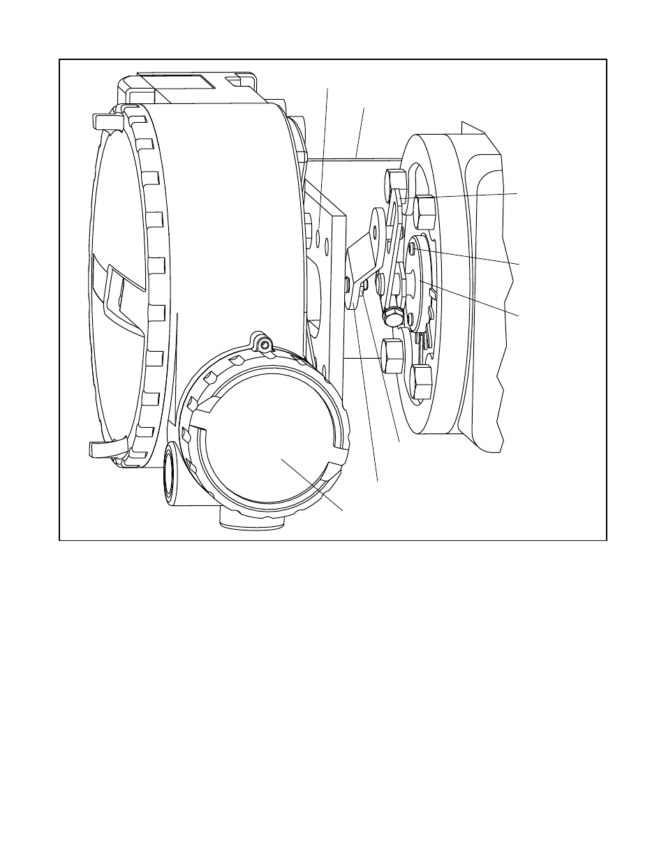
(Figure 14)
The standard rotary mounting applies to valve/actuator
assemblies that do not have mounted volume tanks or
handwheels. The standard mounting uses a linkage
directly coupled to the valve shaft. This linkage is not
affected by misalignment between the positioner and the
actuator.
The tools required for the following procedure are:
two
5
/
16
-inch open-end wrenches
3
/
16
-inch box-end wrench
1
/
2
-inch end wrench phillips driver
1. Fasten spline lever adapter to splined lever using two
No. 6 x
1
/
2
-inch long self tapping screws.
2. Slide take-off arm assembly onto spline lever adapter
shaft and tighten nut with
5
/
16
-inch end wrenches so
arm is snug on shaft but still able to rotate. This will
Figure 14: Standard Rotary Mounting
Positioner Bolts
1
/
4
-20 (4)*
Bracket Bolts
5
/
16
-18 (2)
* Located in appropriate
hole pattern as indicated on
bracket. (25, 50, 100/200)
Follower Arm,
Rotary
Lock Washer (2)
Bolt No.10-32
Nut No.10-32
Self Tapping
Screws (2)
Spline Lever
Adapter
Nut No.10-32
Lock Washer
Follower Arm
Logix 1400 Positioner
be tightened after the linkage is correctly oriented.
3. Attach follower arm to positioner feedback shaft
using the star washer and No. 10-32 nut.
4. Using four
1
/
4
-20 x .50 L. bolts and
7
/
16
-inch box
wrench, fasten positioner to universal bracket using
appropriate hole pattern (stamped on bracket).
5. Using a
1
/
2
-inch box wrench and two
5
/
16
-18 x .50 L.
bolts, attach bracket to actuator transfer case pad,
noting that the take-off arm pin must slide into slot on
follower arm. Leave these bolts slightly loose until
final adjustments are made.
6. Adjust bracket position noting the engagement of the
take-off arm pin and the follower arm slot. The pin
should extend approximately
3
/
16
-inch past follower
arm. When properly adjusted, securely tighten the
bracket bolting.