3 valves with ptfe seat rings – Flowserve Trunnball DL Ball Valves IOM User Manual
Page 7
7
NAF Trunnball DL Ball Valves NFENIM4168-00-A4 01/15
flowserve.com
4 Remove the ball (3), trunnion plates (21) and bearing washer
(25), which is simple to do when the valve is in the closed position.
See Figure 4.
5 Remove the trunnion plates (21), trunnion bearing (23) and
bearing washer (25) from the stub shafts of the ball (3).
6 Carefully inspect the ball (3) and seat rings (4).
7 Clean all parts thoroughly. First use hot water and then
degreasing agent, if necessary. Don’t scrape any of the machined
surfaces with hard tools.
8.3 Valves with PTFE seat rings
1 To ensure tightness of the valve, change the seat rings (4),
springs (24) and seat seal (15) if they are worn or damaged.
2 For the main body (1): Fit seat seal (15) into the groove in the
main body (1) and place the spring (24) into the seat area. Put
some silicone grease on the surface of the seat seal (15) and
gently press the seat ring (4) down.
3 For the body cover (2): Fit seat seal (15) into the groove in the
body cover (2) and place the spring (24) into the seat area. Put
some silicone grease on the surface of the seat seal (15) and
gently press the seat ring (4) down.
Note: If the valve is intended for service in an oxygen system a
grease suitable for oxygen service must be used
4 Inspect the ball (3). Minor damage to the sealing surface can be
removed by polishing with fine emery cloth. If the ball has major
damage, it must be replaced to ensure satisfactory tightness.
5 Fit a new trunnion bearing (23) in each of the trunnion plates
(21).
6 Place a new bearing washer (25) onto each of the stub shafts of
the ball. Directly thereafter put the trunnion plates (21) over the
bearings washer (25) on each side of the ball (3).
7 Place the main body (1) on a work bench with the pipe flange
facing down. Lower the ball (3), including the trunnion plates
(21), into the main body (1) see Figure 4. Make sure that the four
pins (22) are still fitted in the main body (1) with the tapered end
facing up, and check that the pins enter into the corresponding
holes in the trunnion plates (21).
8 With the ball assembly in place in the main body (1), put the
remaining four pins (22) into the trunnion plates (21) with the
tapered end facing up.
9 Put a new body seal (14) on the body cover (2) so the sharp end
will face the main body (1) when assembled.
10 Lower the body cover (2), onto the main body (1). Note: The
main body (1) and body cover (2) will only fit in one position.
11 Lubricate the contact surfaces of the nuts (19), and the threads
of the studs/bolts (17, 18), with suitable anti-seizing grease and
put the nuts onto the studs/bolts.
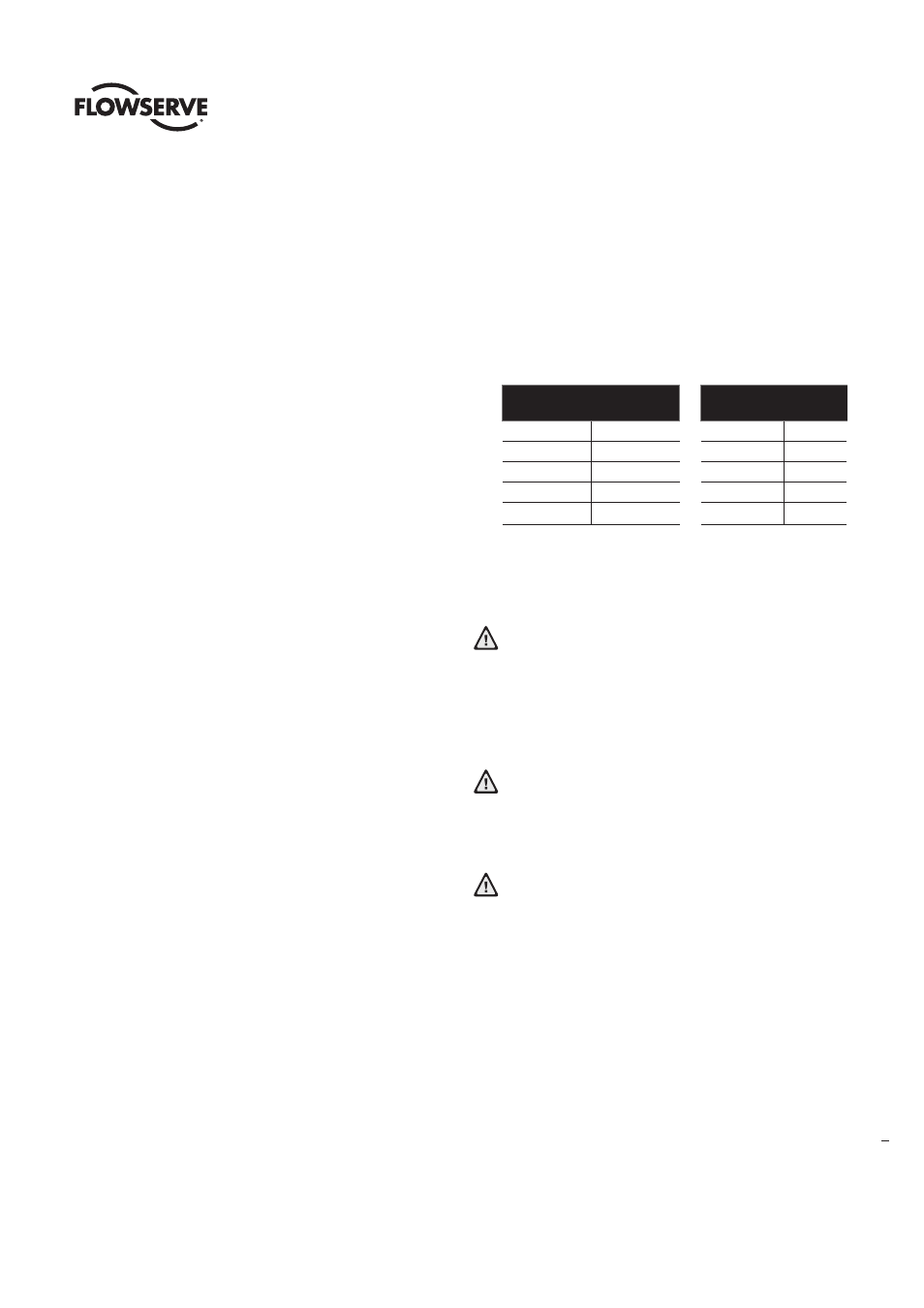
12 Tighten the bolted joint of the two body halves (1, 2) alternately
in several stages, and finally tighten according to the torque as
below.
13 Operate the valve between closed and open positions.
14 If possible, pressure test the valve with water to check its tightness.
See Figures 5 and 6.
Testing with gaseous media is not recommended due to
safety issues. Make sure that the cavities of the valve are
properly filled with liquid before pressure testing. This
is most easily done by placing the valve in the vertical
position and filling the valve in the semi open position with
liquid.
Testing the valve body tightness (5) should not be
performed at a pressure higher than 1.5 x maximum
allowed working pressure. Refer to Technical Bulletin
NFENTB4168
Testing of the ball and seat tightness (6) should not be
performed at a pressure higher than 1.1 x maximum
allowed differential pressure (see Technical Bulletin).
As the seat needs a certain amount of flow to seal against
the ball, we recommend that the inlet pipe connection is a
minimum of 25 mm/1”.
15 If the valve has been pressure tested, please check and, if
needed, re-tighten the bolts according to 8.3.12.
Bolt
Torque Nm
Bolt
Torque
Nm
M12
76
UNC 1/2”
89
M16
187
UNC 5/8”
175
M20
364
UNC 3/4”
308
M24
629
UNC 7/8”
493
M30
1240
UNC 1”
737