Vogt valves – Flowserve Vogt Forged Steel Gate User Manual
Page 23
Flow Control
Vogt Valves
FCD VVENIM2000-02
Forged Steel Gate, Globe and Check Valves
23
2. When the total valve must be furnace heated as part of a piping
subassembly to PWHT temperature, the following procedure is
recommended:
A. Disassemble valve. Remove gate/disc, piston, gasket and
bonnet assembly. The seat rings in gate valves cannot be
removed and must be left in place.
B. For a gate valve, during disassembly the gate and body
shall be marked to ensure that the same gate goes back
into the same valve body in the same orientation as it was
when it was removed. The gate shall not be rotated when
reassembled.
C. Replace the bonnet gasket during assembly following PWHT.
D. The furnace for PWHT should be a controlled atmospheric
type to ensure that heat treat scale does not develop that
can adversely impact the gasket faces and/or threaded
features of the valve.
3. Additionally, the above disassembly procedure may also be
used with localized heating equipment, at the option of the heat
treat provider.
The above represents our best recommendation but does not
constitute a guarantee that the valve will not suffer some dam-
age as a result of PWHT.
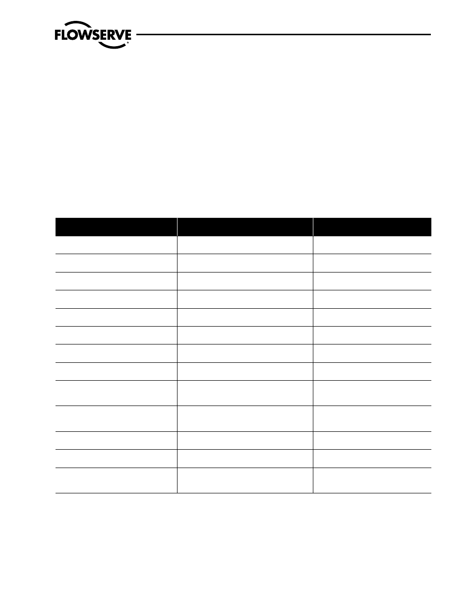
The following table offers recommendations relating to valves
installed in horizontal and vertical pipes.
Recommended Valve Orientation
Valve Type
Stem Orientation
Horizontal Line
(1)
Stem Orientation
Vertical Line
(2)
Gate
Any (except vertical down)
Preferred vertical stem upright
Any Preferred stem horizontal
Gate valve
(3)
Motor/air-operated
Any (except vertical down)
Preferred vertical stem upright
Any Preferred stem horizontal
Globe-T pattern
Any (except vertical down)
Preferred vertical stem upright
Any Preferred stem horizontal
Globe-T pattern
(3)
Motor/air-operated
Any (except vertical down)
Preferred vertical stem upright
Any Preferred stem horizontal
Globe-Y pattern
Any
Preferred stem at ±50° to pipe run in upright position.
Any
Preferred stem at ±50° to normal of pipe run
Globe-Y pattern
(3)
Motor/air-operated
Any
Preferred stem at ±50° to pipe run in upright position.
Any
Preferred stem at ±50° to normal of pipe run
Angle
Any (except vertical down)
Preferred stem vertical upright
Any
Preferred stem vertical upright
Angle
(3)
Motor/air-operated
Any (except vertical down)
Preferred vertical stem upright
Any
Preferred stem vertical upright
Ball or Piston lift check valve-T pattern
(no spring) (includes stop check valve)
Preferred vertical
Upright
Rotation off top dead center ±40°
Not recommended
Ball or
Piston lift check valve-T pattern
(spring-controlled)
Preferred vertical upright
Rotation off top dead center ±90°
Any
Piston lift check valve-Y pattern
(spring-controlled)
Preferred vertical upright
Rotation off top dead center ±90°
Any
Swing check valve
Preferred vertical upright
Rotation off top dead center ±30°
Any, but upward vertical flow required
Stop check valves
Preferred vertical
Upright
Rotation from top dead center ±40°
Not recommended
General:
• Gate, globe, angle, and spring-controlled check valve designs oriented with
stem or body run vertical down orient the valve body cavities in such a
matter that debris can be collected and not get flushed out. This may cause
unreliable valve operation. A vertical stem down or body run down orienta-
tion is not recommended for fluid service that may include debris.
• Recommended orientation of motor/air-operated valves may be changed by
the recommended orientation of the actuator.
Notes:
(1)
A ±5° variation off horizontal for the pipe would not change the recom-
mendation except for swing check valves. This valve design will not close
by gravity if the piping is off horizontal, which allows the swing check
mechanism to swing away from the seat.
(2)
A ±5° off variation vertical for vertical piping does not change the recom-
mendations in the table.
(3)
For small-bore socket welding and threaded valves equipped with a motor
or air operator mounted in a horizontal plane, it is recommended that
external supports be added to the piping arrangement to remove the load
from the connecting socket welds or threads of the valve.