10 postweld heat treat (pwht) recommendations, Vogt valves – Flowserve Vogt Forged Steel Gate User Manual
Page 22
Flow Control
Vogt Valves
22
Forged Steel Gate, Globe and Check Valves
FCD VVENIM2000-02
4.9 Recommendations for Field
Welding of Small Stainless
Steel Socket Weld Valves
1. Evaluation of Code Requirements Prior to welding, construc-
tion code requirements should be reviewed (ASME Section I,
VIII, IX, ANSI B31.1, B31.3, etc.). Applicable code requirements
may supersede these recommendations. In the absence of
specific code requirements, the guidelines of ASME Section IX
are recommended for qualification.
2. Selection of Process Based on the size of the valve and the
skill of the welder, either the SMAW (stick) or GTAW (Tig) pro-
cess is recommended. SMAW is generally preferred, although,
GTAW offers more control (at the expense of speed) and may be
preferred for 3/4" and smaller valves.
3. Selection of Weld Filler Metal For SMAW, use 3/32" elec-
trode on the first pass with 1/8" for subsequent passes. 1/8"
and 5/32" electrodes may be used effectively on larger valves.
E316L-16 electrodes are recommended.
3
/
32
" type ER316L is recommended for GTAW.
1
/
16
" and
1
/
8
" may
also be used successfully.
4. Selecting the Welder Most construction codes require a
welder to qualify prior to making a production weld. Welder
performance qualification provides some assurance that the
production weld will be of good quality since the welder has
proven, through testing, that he can make a good weld. Care
should be taken in comparing the welder’s qualification with the
code requirements to assure that the welder has qualified with
an appropriate test for the intended production weld.
5. Joint Cleanliness The area in-way-of welding should be
cleaned to remove, dirt, oil, and protective coatings. This should
be done prior to fit-up or residue in the joint overlap will not
be removed. Sanding, grinding, or wire brushing is usually
adequate. Solvents may be necessary, if oil is to be removed.
6. Fit-up (Socket Weld Valves) In order to gauge fillet weld size
after welding, place a circumferential mark 1" from the engaging
pipe end prior to welding. Bottom out the pipe engagement into
the socket and pull it back approximately 1/16" to allow for weld
shrinkage. Note the dimension from the mark to the valve pipe
end.
Tack welds should be contoured to allow for easy inclusion into
the final weld.
7. Welding Technique
a. Prior to welding, the valve should be lightly closed. Where pos-
sible, attach the electrical ground to the adjoining pipe on the
same side of the valve as the weld being made. Do not attach
the ground to the handwheel or upper structure of the valve or
arcing across the valve seating surfaces could occur.
b. Where possible, welding should be done in the flat or
horizontal position. Where vertical welding is necessary,
progression should be upward (vertical down welding is
prone to lack-of-fusion).
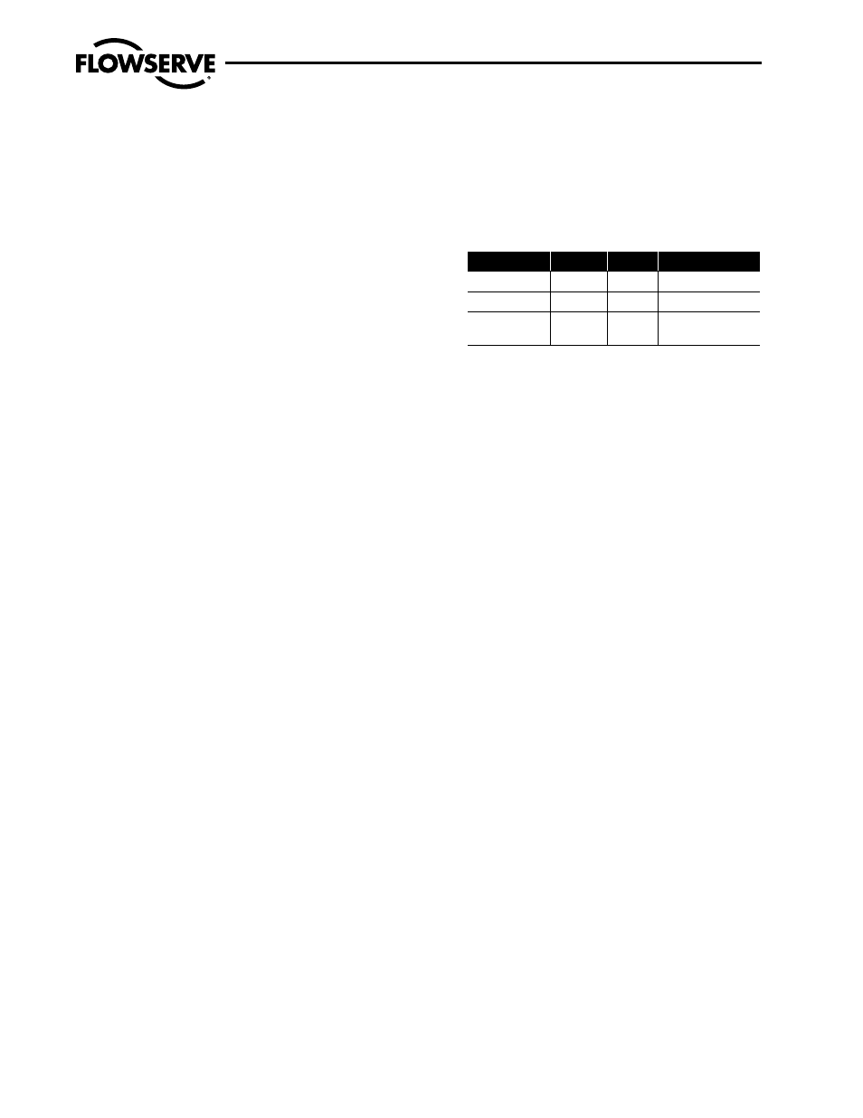
c. Welding parameters: The following welding parameters may
be used as a guide:
Electrode
Current
Voltage Shielding Gas
3
/
32
" E316L-16
70-90 A
*
N/A
1
/
8
" E316L-16
90-110 A
*
N/A
3
/
32
" ER316L
75-100 A
13-14 V 100% Argon at
15-20 CFH
*Use as close and tight an arc as possible.
d. A minimum of two layers should be used for all socket
welds. This will decrease the chance of leaking even if one
pass contains a weld defect.
4.10 Postweld Heat Treat (PWHT)
Recommendations
The following recommendations are offered as they relate to the
performance of postweld heat treatment on socket-welded or butt-
welded valves during the installation stage.
Please note that ASME B31.1, B31.3, Section VIII and most other
piping codes do not require PWHT of Vogt-designed ASTM A105,
A182F11 class 2, F22 class 3 and F316/316l valves. Vogt F11 chem-
istry is restricted to meet the conditions for waiver of PWHT for this
material in most ASME piping codes.
For assembled valves (seal-welded design*):
1. Lightly close the assembled valve.
2. Use only localized heating equipment.
3. Do not wrap or insulate total valve during PWHT.
4. Wrap the localized heating equipment around the welded joint
and heat to the desired temperature for the desired length of
time.
5. Furnace heating of the total valve assembly, as part of a piping
subassembly, is completely unacceptable. As supplied valve trim
part material conditions can be impacted by this requirement
and the packing and gasket may be damaged or destroyed.
* Vogt seal-welded design valves cannot be disassembled without removal of
the seal weld. A seal-weld valve design should not be used if the valve must
be part of an assembly undergoing PWHT in a furnace. For this application,
a bolted bonnet design valve should be used.
For bolted bonnet valves (disassembly permitted):
1. Localized heating equipment is preferred for the PWHT of these
valves as well and the PWHT can be done with the valve fully
assembled per the instructions above.