Adjusting the minimum pressure cutoff feature – Flowserve XL90 Series User Manual
Page 6
WARNING: Be certain power to I/P module is disconnected
before removing housing cover in explosive atmospheres;
otherwise personal injury may occur.
3. Before adjusting the zero and span, be certain the MPC fea-
ture is disabled. Refer to Step 7 in the ‘Adjusting the
Minimum Pressure Cutoff Feature’ section.
4. Connect a current source to the terminal block on circuit
board.
NOTE: The zero and span adjustments are multi-turn potentio-
meters (pots) that have no stops on the ends of their travel;
however, they have a slip clutch to prevent damage from over-
adjustment. The pots also make a clicking noise when they
have reached adjustment limits.
5. Apply a 4.0 mA signal to the input. Locate and adjust zero
trim pot to achieve a 3.0 psi output. The output will increase
with clockwise rotation of the zero trim pot. If calibrating an
I/P module with a 10-50 mA input signal, apply a 10.0 mA
signal to input.
6. Increase input signal to 20.0 mA (50 mA for 10-50 mA
units). Locate and adjust span trim pot to achieve a 15.0 psi
output. The output will increase with clockwise rotation of
the span.
7. Recheck zero setting by repeating Step 5. The span adjust-
ment may affect zero setting.
8. Repeat Steps 5, 6 and 7 until proper adjustments are
obtained.
Adjusting the Minimum Pressure Cutoff Feature
The XL90 positioner with I/P Transducer has a “Minimum
Pressure Cutoff” (MPC) feature, which allows the user to set
the positioner. When the input signal falls below a user-
adjustable current, the pressure output falls rapidly to approxi-
mately 1.7 psi, causing the valve to move to the failure position.
This feature is generally used when the service requires a tight
shut off or to prevent throttling near the valve seat. To adjust this
feature, refer to Figure 9 and perform the following :
NOTE: The following procedure applies only when the mini-
mum pressure cutoff feature will be used.
NOTE: The zero and span settings of both the positioner and
I/P transducer should be verified as accurate before the min-
imum pressure cutoff feature is enabled and adjusted.
1. Connect the I/P module to a 30 to 150 psi air supply
pressure.
48-6
Flowserve Corporation, Valtek Control Products, Tel. USA 801 489 8611
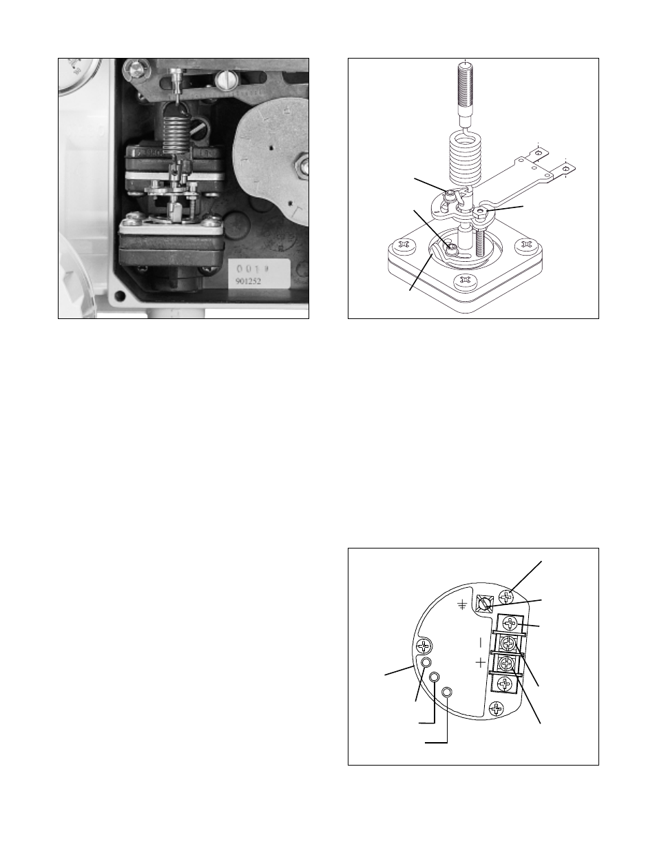
Figure 7: Close-up of Gain Adjustment
Figure 8: Gain Adjustment
ZERO
SPAN
MPC
INTERNAL PARTS
NO SERVICEABLE
FLOWSERVE
SERIAL NUMBER
Figure 9: NT 3000 Circuit Board Module
(housing cover removed)
Upper
Lock Screw
Lower
Lock Screw
Adjust Lever
Spacer Nut
(Do not loosen)
RFI Can
Zero Adjustment
Span Adjustment
Minimum Pressure
Cutoff Adjustment
Circuit Board
Mounting
Screws
Grounding
Screw
Terminal
Block
Current
Loop (-)
Termination
Current
Loop (+)
Termination