Seal chamber requirements – Flowserve P-50 Durametallic User Manual
Page 3
3
Seal Chamber Requirements
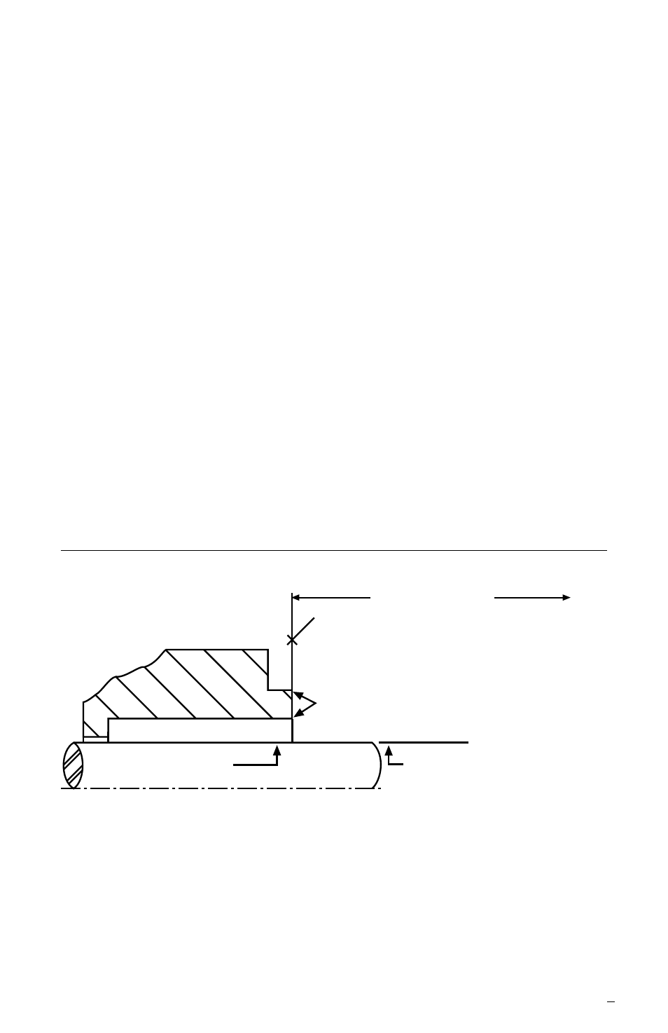
Figure 1
1.5 Check equipment dimensions to ensure that they are within the
dimensions shown in Figures 1 and 2. Critical dimensions include
shaft or sleeve OD (A), a chamber depth of at least 25.4 mm
(1.000 inch), minimum and maximum seal housing bore (B), and
the minimum distance to the first obstruction (F).
1.6 Check gland bolting to ensure that bolt diameter and bolt circle
conform to he dimensions shown in Figure 2.
1.7 Handle the P-50 with care, it is manufactured to precise
tolerances. The stationary and rotating sealing faces are of
special importance. They are lapped flat to within three light
bands (34.8 millionths of an inch). Keep the seal faces perfectly
clean at all times.
To first obstruction
Face of seal housing to be square to the
axis of the shaft to within 0.0005 mm/mm
(0.0005 inch/inch) of seal chamber bore TIR
and have a 1.6
μ
m (63
μ
inch) R finish or better
a
Gland pilot can be at either of these
register locations, concentric to within
0.125 mm (0.005 inch) of shaft or
sleeve OD TIR
Seal housing bore to have 3.2 μm
(125 μinch) R finish or better
Sleeve or shaft finish to be
0.8 μm (32 μinch) R or better
a
a
• Bearings must be in good condition
• Maximum lateral or axial movement of shaft (end play) = 0.25 mm (0.010 inch) TIR
• Maximum shaft runout at face of seal housing = 0.05 mm (0.002 inch) TIR
• Maximum dynamic shaft deflection at seal housing = 0.05 mm (0.002 inch) TIR
Shaft or sleeve OD
+0.000 mm (+0.000 inch)
-0.050 mm (-0.002 inch)
+0.000 mm (+0.000 inch) API 610/682
-0.025 mm (-0.001 inch) DIN/ISO
ANSI