Flowserve MSS User Manual
Page 12
1
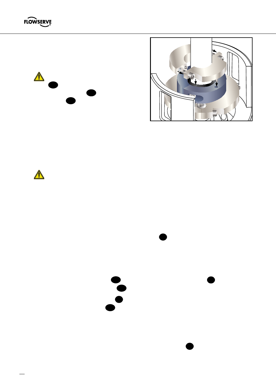
0.1“ (3 mm) spring gap is achieved
using the two 1/8“ Allen wrenches as
spacers. Tighten the shoulder screws
completely and lock seal drive to shaft.
Designs that incorporate set screws
57
in the seal drive, after tightening
sholder screws
K1
, tighten the set
screws
57
to lock the seal drive to
the shaft.
The seal is now ready for operation.
See paragraph 8.0, „Starting up the
Machine“, before start-up.
!
Once more check the running pre-
cision as per paragraph 5..6 and the installation dimensions according the
assembly drawing.
The installation dimensions of the mechanical seal type MSS must apply to the
dimensions shown on the assembly drawing. Non-compliance of the information
shown on the assembly drawing may cause in damages.
!
For special problems encountered during installation, contact your nearest
Flowserve Sales and Service Representative or Authorized Distributor.
6.13 Installation of Non-Piloted MSS (see Figure 3).
6.14 Spray one end of the split gland gasket O-ring
G
with the adhesive accelerator
provided. Apply one drop of the adhesive provided to the other end. Position the
split O-ring around the shaft and bond the joint ends together. Hold for one minute
to assure a suitable bond. Lubricate the O-ring with the silicone lubricant provided.
Place the bonded O-ring on the seal chamber (stuffing box) face.
6.15 Remove the retainer halves
RP
from the face of the gland halves
1
and save the
retainer halves and cap screws
K3
for Step 6.0.
6.16 Position the gland ring halves
1
around the shaft and fasten them loosely together
using the shoulder screws
K
provided.
6.17 Use some silicone lubricant provided to hold the gland gasket O-ring in its groove
and position the gland on the seal chamber face by loosely tightening the nuts or.
(See paragraph 6.7).
6.18 Bond one of the split stationary face seat gasket O-rings
6
and lubricate as in
Step 6.14. Place the bonded O-ring in the gland counterbore.
Mount seal drive halves and set spring gap
Reference 6.1