Flowserve MSS User Manual
Page 11
11
Split Mechanical Seal MSS - Installation and maintenance instructions for machinery parts
the seal chamber face for the inner stationary face O-ring to form a seal. The
gland face must, however, be square with the axis of the shaft to within 0.00“
FIM.
Components provided by the customer for installing the mechanical seal type
MSS, e.g. fastening screws, must prove adequate both in the choice of material
and the dimensions. It must not be possible to overstress these components, e.
g. the max permitted tightening torque must not be exceeded.
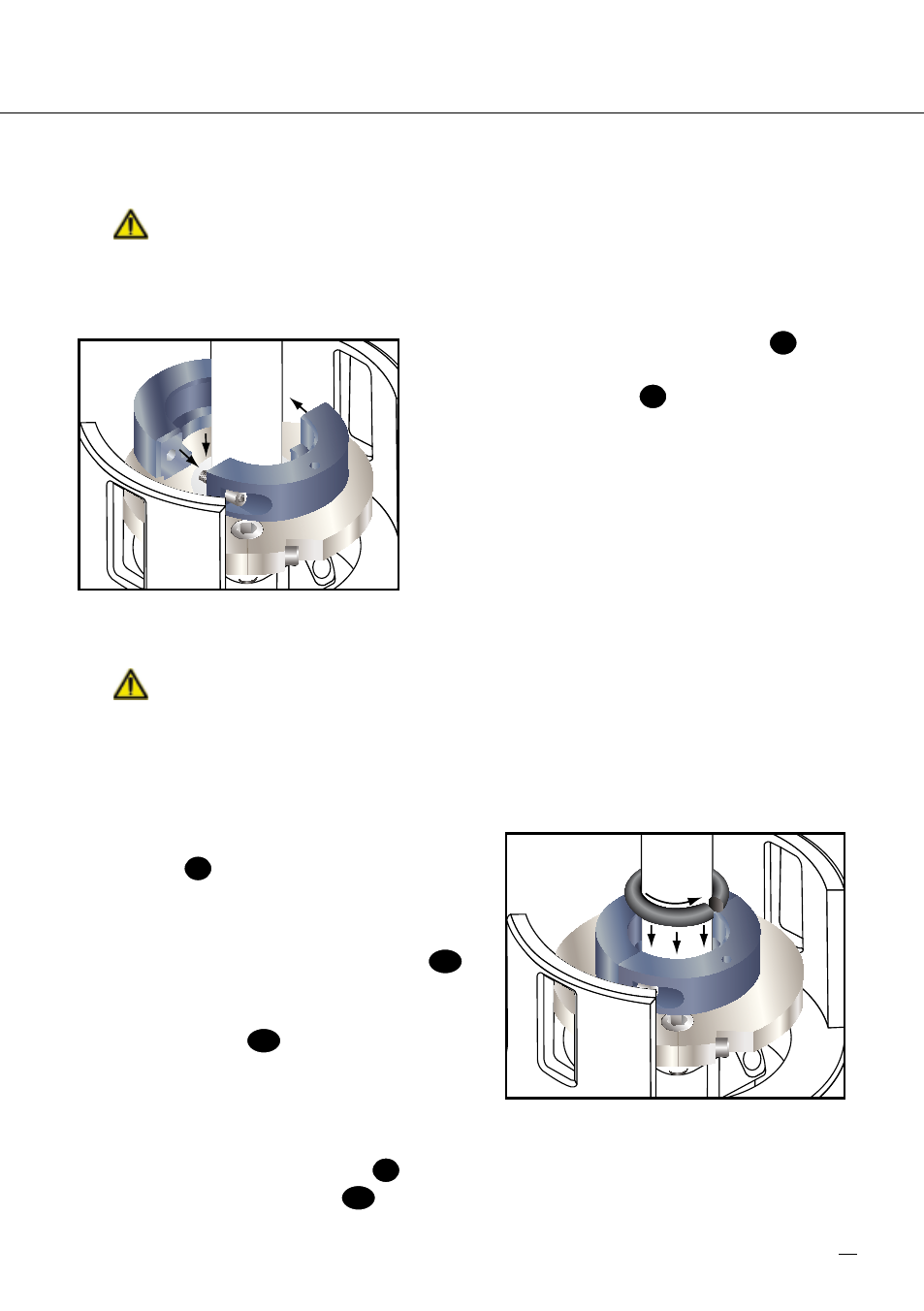
6.8 Mount the rotating seal face halves
3
around the shaft and fasten them together
using the cap screws
K
provided, tighten to
a 30 lb-in (3.4 Nm) torque maximum. Check
for seal face joint mismatch. If any mismatch
exists, loosen the cap screws and shift the
rotating seal face halves until no mismatch is
felt. Retighten the cap screws.
Note: There are threads on both halves of the
rotating seal face. Align halves carefully so
as to not allow a gap between halves during
tightening.
The shaft sleeve can be displaced in radially or axially direction, if the seal drive
connection is not accomplished according the requirements.
6.9 Clean the rubbing faces of the stationary face and rotating face ring with alcohol
and place the rotating face so that its rubbing face is against the stationary face rubbing
face.
6.10 Position the split rotating face gasket
O-ring
P
around the shaft, bond and
lubricate as in Step 6.3, and push the
O-ring into the rotating face bore.
6.11 Install the white split backing ring
P1
into the rotating face bore next to the
O-ring. Install the two black elastomer
backing rings
P
. Be sure to stagger
the backing ring joints by 10° .
!
Do not bond the backing ring joints
together or with each other.
6.1 Mount the seal drive halves
5
around the shaft and loosely fasten them together
with the shoulder screws
K1
provided. Line up the pins in the seal drive with the
holes in the rotating face and slide the seal drive towards the rotating face until a
Reference 6.8
Reference 6.10