Flowserve Polybase baseplates User Manual
Page 17
Polybase Baseplate INSTRUCTIONS ENGLISH 71569284 – 12-10
Page 17 of 24
flowserve.com
5) For stilt mounts, the type and number
must be specified
If the spare Polybase baseplate is intended to
be used with equipment which is or will be installed in
a potentially explosive atmosphere, Flowserve should
be given the complete ATEX classification of the
equipment in order to check compliance.
6.3 Recommended spares and
consumable items
There are no recommended spare parts for the
Polybase baseplate. In the rare instances when a
threaded insert needs to be replaced or a Polybase
baseplate needs to be drilled and inserted for a
different size motor, the following materials and
procedure would apply.
6.4 Tools required
For drilling holes in the Polybase material, use a
masonry bit or a carbine-tipped drill bit.
6.5 Field thread insert installation
procedure
The procedure detailed below may be used either to
replace a damaged original thread insert or to install
an insert in a new location.
Thread inserts properly installed in the field
will yield performance characteristics and service life
equivalent to inserts installed at the factory. Field
installation should only be undertaken when
absolutely necessary, and then only by qualified
personnel using suitable drilling equipment. In order
to achieve a successful installation the following
procedures must be followed PRECISELY and the
drilling operation must be carried out AS
ACCURATELY AS POSSIBLE.
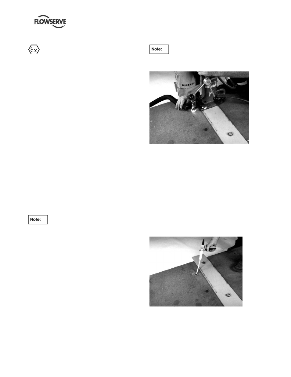
a) Drill out the damaged insert (or drill a new hole in
a location that has been carefully laid out) taking
care not to enlarge or elongate the hole into
which the replacement insert will be installed. It
is critical that the hole be drilled perpendicular to
the surface of the Polybase and that the hole
center line location be maintained. The
recommended method for achieving this is to use
a carbide tipped bit with a magnetic base drill
mounted on a steel plate that has been bolted to
the adjacent inserts in the baseplate (see Figure
6.1). Correct drill diameters and depths are
shown in Table 6-1.
DO NOT USE OIL OR CUTTING FLUID -
HOLES MUST BE DRILLED DRY.
Figure 6.1
b) Remove all dust and metal chips from the drilled
hole using dry, oil-free compressed air.
c) If the drilled hole has become contaminated with
oil or other foreign substance, flush thoroughly
with acetone or ethyl acetate and dry completely
with oil-free compressed air.
d) If the replacement insert has been contaminated
with oil or other foreign substance, flush
thoroughly with acetone or ethyl acetate and dry
completely with oil-free compressed air.
e) Dispense adhesive into the drilled hole (see
Figure 6.2) following the instructions provided.
Fill the hole to within approximately 12 mm (1/2
inch) of the baseplate surface.
Figure 6.2
f) After applying oil to the threads of a properly
sized socket head cap screw (or hex head bolt),
thread it into the insert. Be careful not to get any
oil on the outside surfaces of the insert.